Flowserve F75 Series Fail-Safe Module User Manual
Series f75 fail-safe module, Description, Installation and wiring
Worcester Actuation Systems
WCAIM2029
(Part 16022)
Series F75 Fail-Safe Module
Installation, Operation and Maintenance Instructions
CAUTION: Flowserve recommends that all products that must be
stored prior to installation be stored indoors, in an environment
suitable for human occupancy. Do not store product in areas where
exposure to: relative humidity above 85%, acid or alkali fumes,
radiation above normal background, ultraviolet light, or
temperatures above 120°F or below 40°F may occur. Do not store
within 50 feet of any source of ozone.
1. DESCRIPTION
The Series F75 Fail-Safe Module is designed to be coupled with
Worcester/McCANNA’s Series 75 electric actuators:
• Series 20 F75 Module with Size 10 to 23 Series 75, 24 VDC Actuator.
Normal operation is accomplished utilizing a 120 or 240 VAC supply
voltage to power the Series F75 module. The module converts the AC
power to 24 VDC power, which is used to power the Series 75 actuator.
Upon loss of supply voltage, the Series F75 module latches out the
supply side circuitry and switches over to battery power to drive the
valve to the predetermined failure position. When the supply voltage
is returned, the Series F75 module can be returned to normal
operation by depressing the “RESET” switch on the face of the
module’s enclosure.
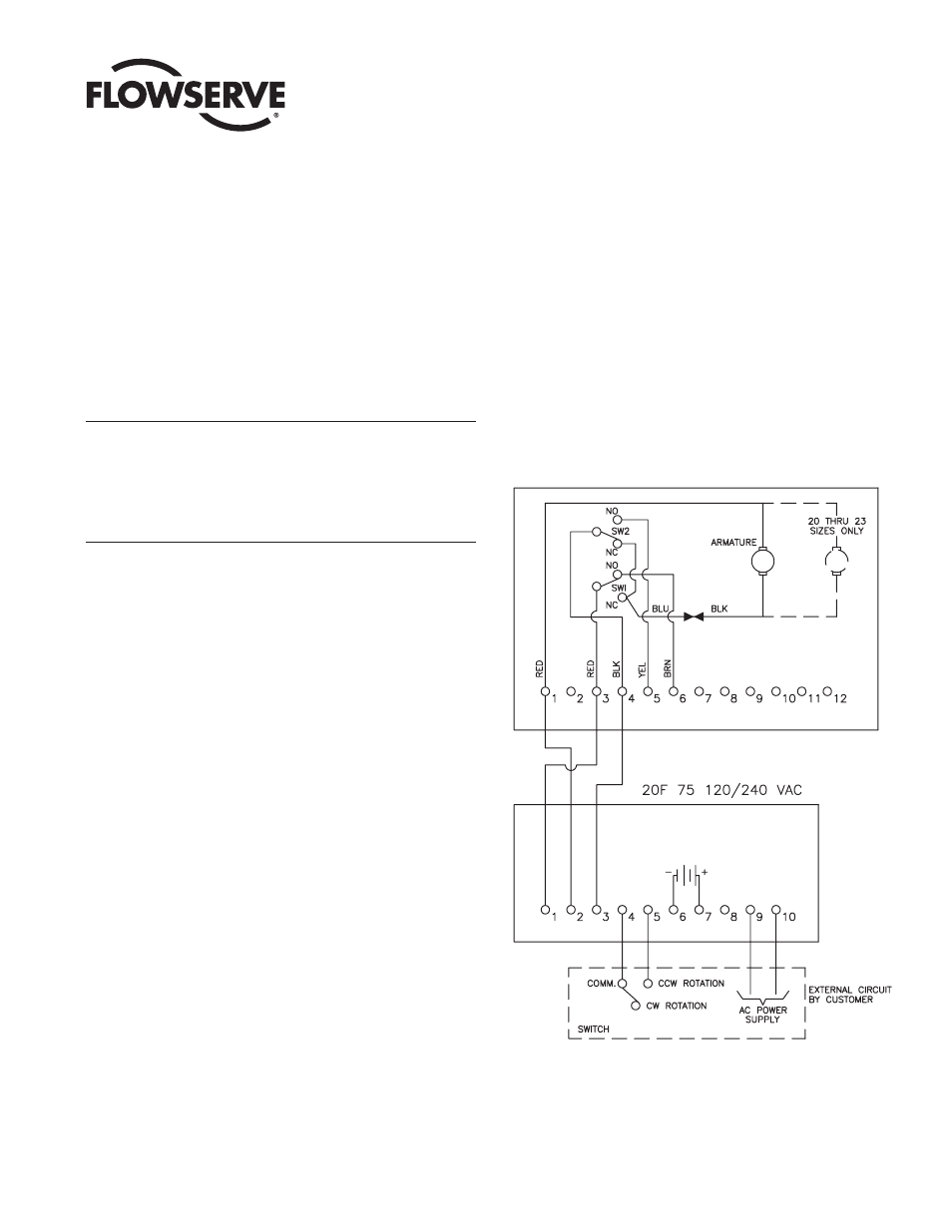
2. INSTALLATION AND WIRING
2.1 The Series F75 Module can be installed adjacent to or remote
from the actuator depending on requirements of the application. It
should be suitably mounted by the user in a well-ventilated area.
A small vent is located in the base of the enclosure to allow
venting of any battery gases should they occur. Batteries are of
the sealed type and, under normal charge/discharge usage, no
outgassing should occur. Replacement batteries should be of the
same or equivalent type.
IMPORTANT: If actuator is located in a hazardous location, the
F75 module must be remotely located away from this area.
Proper, standard industry practices should be used in wiring
Series F75 Module to actuator. Consult Figure 1 and Figure 3.
Wiring is shown for fail-safe close, fast mode. For other failure modes,
consult page 2.
Figure 1 – Worcester/McCANNA 10-23/75 24 VDC Actuator