Worcester controls – Flowserve 90 Series Controller User Manual
Page 5
WCAIM2045
Positioner/Controller for Series 90 Modular Accessory System
5
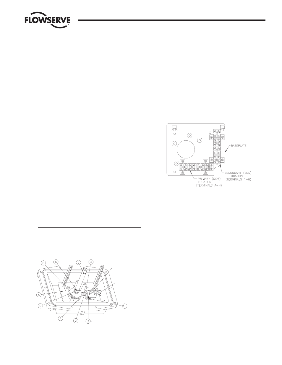
4. The correct power source (120 VAC or 12/24 VDC) is
connected to terminals 1 (neutral/negative lead) and
2 (hot/positive lead) of the terminal strip located on the front
edge of the M.A.S. baseplate. The correct source voltage is
noted on the M.A.S. product label. See caution in section 1,
paragraph b.
c. Mounting the Potentiometer
The controller version of the M.A.S. requires either a
4-20 milliamp or 1000 ohm setpoint signal for operation depending
on the option purchased. If the 1000 ohm setpoint option is being
used, an appropriate potentiometer will be supplied with the unit.
The potentiometer will be shipped inside the housing and may be
mounted in any location external to the M.A.S. (i.e., a control room).
The positioner version of the M.A.S. circuit board requires a
feedback potentiometer to be installed on the M.A.S. baseplate.
Refer to Figure 3 below. This potentiometer is geared to the
M.A.S. shaft and provides the position feedback signal to the
M.A.S. positioner circuit board.
1. With the potentiometer (item 3) mounted to the potentiometer
bracket (item 4) and the pinion gear (item 1) loosely fitted to
the potentiometer shaft (item 2), mount the potentiometer
bracket (item 4), if not already mounted, to the baseplate
(item 5) using two #8-32 x
B\zn screws (item 10) provided.
The three (or six) leads on the pot should be oriented up or
towards the two circuit board mounting posts.
2. Remove the upper snap ring (item 6) from the shaft (item 7).
Use care to avoid deforming it permanently.
3. Slide the face gear (item 8) onto the shaft, teeth facing down,
and secure with the snap ring (item 9) provided.
Note: The face gear utilizes a friction fit to the shaft. For best
results, wipe off any lubricant that may be on the shaft before
sliding on the face gear.
Caution: Do not overstretch the snap ring; use the minimum
opening to allow it to slip over the gear.
4. Replace the upper snap ring (item 6).
5. Add the second terminal strip in the “secondary” location
using the four #4 x
C\," self-tapping screws provided. See
Figure 4 below.
6. Wire the potentiometer to the terminal strip as shown in the
wiring diagram for the appropriate option. Refer to Section 11
for wiring diagrams.
Important: Voltage limit of the potentiometer is 30 volts
maximum.
Note: All wiring is to be run smoothly and neatly and away
from any rotating parts, using wire ties if necessary. Use
caution to avoid pinching wires and/or solenoid rectifiers
between cover and base of flanges. All wiring to terminal
strips should be inserted only to mid-point of terminal strips.
7. Adjusting the Feedback Potentiometer
Prior to adjusting the potentiometer, the M.A.S. package must
be mounted to the actuator, and the baseplate must be
installed in the M.A.S. unit. Adjust the potentiometer pinion
gear so that there is approximately
Z\zn" tooth engagement
between the face gear and the pinion gear and tighten the
pinion gear set screw. The actuator must be in the full-closed
position prior to making the potentiometer adjustment. In the
case of a double-acting actuator, either temporarily connect
air to the appropriate actuator port or use a wrench to move
the actuator to the closed position. Unless there is air
supplied to a spring-return actuator, it should automatically
be in the closed position. Using an ohmmeter, measure the
resistance between the purple and white/black potentiometer
leads at the terminal strip. There should be no power applied
to the M.A.S. board (if already installed) during this
measurement. Rotate the face gear to obtain a resistance
reading on the ohmmeter of 80 to 90 ohms.
Note: It is not necessary to loosen or remove face gear snap
ring to rotate gear.
Important: The feedback potentiometer is calibrated for only
one 90 degree quadrant of valve operation. If the output shaft
is repositioned to another 90 degree quadrant, or if the output
shaft is rotated a multiple of 360 degrees from its original
position, or if the M.A.S. package is removed from the
actuator, the feedback potentiometer will no longer be in
calibration and must be recalibrated as directed in above,
section 6.c.7. (Also see section 1, paragraph d).
Flow Control Division
Worcester Controls
Figure 3
"A" Potentiometer
Leads
"B" Potentiometer
Leads
(Dual Potentiometer Shown)
Figure 4