Worcester controls – Flowserve Electri-SAFE DataFlo Digital Electronic Positioner User Manual
Page 5
WCAIM2025
Electri-SAFE DataFlo Digital Electronic Positioner
5
Flow Control Division
Worcester Controls
Do not replace the positioner cover until the unit has been calibrated
and the unit is operational. See the paragraph for Calibration and
Adjustment.
DP72-5V, DP72-XV- Direct Voltage Input Signal for Digital Positioner
This Positioner is available for use with the standard direct voltage
signals: 0 to 5 VDC or 0 to 10 VDC. The Positioner board is factory
calibrated for one of these two signal ranges and field changes are
not advised.
Comparison of resistance measurements made at terminals B and C
against the resistances shown below provides a quick way to
determine the voltage range for which a particular board is calibrated.
If fuse F1 is blown, an open circuit will be indicated.
0 to 5 volt DC models
approximately 800 ohms
0 to 10 volt DC models
approximately 1100 ohms
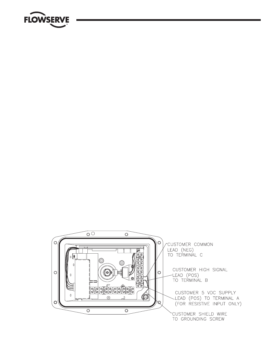
Connect the more positive (+) or “High” signal lead to positioner
terminal B. See wiring label on inside of positioner cover, and/or in
appendix of technical reference manual, and/or wiring diagram below.
Connect the less positive (-) or “Common” lead to positioner
terminal C.
Connect one end of the shield wire to the positioner housing ground
screw. Note that only one end of the shield wire should be connected
to a grounded housing.
Do not replace the positioner cover until the unit has been calibrated
and the unit is operational. See the paragraph for Calibration and
Adjustment below.
CALIBRATION AND ADJUSTMENT
When properly adjusted, the actuator will stop at the full CCW and full
CW positions as a result of having reached one of the respective
limits of the input signal span. The full CCW over travel limit Switch
will be used only as a backup to stop the actuator pump motor should
a failure of an electronic component occur.
Adjustment of Over-travel Limit Switch
The Positioner has been shipped with a limit switch factory calibrated
to stop the actuator in the full CCW position (approx. 92°). It is
located in the actuator housing, behind the flat cover. If it has been
determined that the limit switch requires adjustment, perform the
adjustment as follows:
NOTE: Be very careful when adjusting the switch. It can be damaged
by the actuator switch probe if the switch is adjusted (tightened) too
far in toward the probe. If in doubt of switch position, loosen (back
out) the switch adjustment screw to its loose limit before performing
the following steps.
If not already done, remove the actuator and positioner housing
covers.
When power is first applied, the unit will be in the Run Mode. The
positioner display should be flashing between POS and a number
between 0 and 100.
There are three switches (keys) on the positioner circuit board which
are labeled SEL(black) for select, DN(white) for down, and UP(white)
for up. These are the keys used to calibrate, program, and position
the Digital Positioner Board locally.
On the positioner board, simultaneously press the SEL and UP keys
for three seconds to enter the Manual Mode. The display should
alternate between POS and 0.0.