Worcester controls – Flowserve 10 ACCESS I 39 Actuators User Manual
Page 8
8
10, 15, 20 ACCESS I 39 Actuators
WCAIM2027
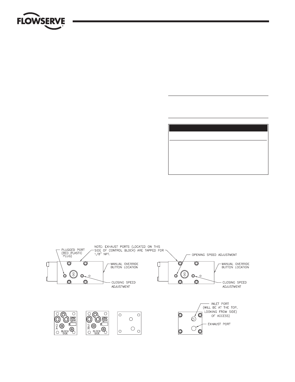
FIGURE 2
SPRING-RETURN
DOUBLE-ACTING
"NO SOLENOID" AIR CONNECTION BLOCK"
GASKET 9A
GASKET 9B
GASKET 9C
g. Proximity Sensor adjustment for “standard” mounting
(no PC Board):
Sensors have to be wired (and powered) per appropriate
wiring diagram. With actuator mounted in “standard”
mounting configuration (see Step 1) and the adjustment
screw near its loose limit, set actuator in closed position
and adjust closed position sensor SW-2 (see Wiring
Diagram) by tightening the adjustment screw until sensor
energizes its load. Then tighten the adjustment screw one
additional turn. Supply power to solenoid, if applicable,
and change actuator to full open position. Adjust the open
position sensor SW-1 in the same manner as the closed
position sensor. When solenoid is de-energized (if
applicable) the actuator will return to the full closed
position. The closed position sensor SW-2 will energize
its load indicating the actuator is in the full closed
position. NOTE: Whenever actuator is in either the closed
or open position, the LED on SW-2 or SW-1 respectively,
will turn on.
h. Proximity Sensor adjustment for “fail-open” mounting
(no PC Board):
With actuator mounted in fail-open mounting
configuration (see step 2) and wired per appropriate
wiring diagram, set actuator in full open position, with
adjustment screw at its loose limit. Adjust open position
sensor SW-2, by tightening the adjustment screw until
sensor energizes its load. Then tighten the adjustment
screw one additional turn. Supply power to solenoid, if
applicable, and change actuator to its full closed position.
Adjust the closed position sensor SW-1, in the same
manner as the open position sensor. When solenoid is de-
energized, if applicable, the actuator will return to its full
open position. The open position sensor, SW-2, will
energize its load indicating the actuator is in the full open
position. NOTE: Whenever actuator is in either the open
or closed position, the LED on SW-2 or SW-1
respectively, will turn on.
4. Wiring instructions for solenoid and/or limit switches
(proximity sensors).
Make electrical connections in accordance with the
appropriate wiring diagram on inside of cover or on the
following pages.
a
WARNING: A load must be used when power is
applied to proximity sensors. Wiring without a load will
cause sensor failure. The load must draw a maximum
of 200 mA at working voltage.
5. Place the lubricated O-ring down over the threaded
section of the housing onto the machined shoulder. The
cover must be threaded onto housing tightly for proper
performance. The assembly is now complete.
NOTE: For units with a metal cover, a light coat of grease
(such as a #1 grease) shall be applied to the cover
threads. A minimum of
Z\c the circumference of the
threads to be lubricated.
Circuit Board Color-Coded Part No. Label Identification
Color
Voltage
Black
120 VAC
Yellow
240 VAC
Green
24 VAC / 24 VDC
Blue
120 VAC (dual voltage)
Red
240 VAC (dual voltage)
Flow Control Division
Worcester Controls
Figure 1
Figure 2