Buswitch, With f – Flowserve BUSwitch User Manual
Page 15
AXAIM020-01
(AUTO-48)
3/03
Page 15 of 16
© 2003, Flowserve Corporation, Printed in U.S.A.
BUSwitch
™
with F
OUNDATION
®
Fieldbus Protocol
Installation, Operating and Maintenance Instructions
Flowserve Corporation
1350 N. Mountain Springs Parkway
1978 Foreman Dr.
Flow Control Division
Springville, Utah 84663-3004
Cookeville, TN 38501
www.flowserve.com
Phone: 801 489 8611
Phone: 931 432 4021
Rel.
Index
Parameter
Factory
Default
Description
acknowledged.
22
DISC_PRI
Priority of the discrete alarm.
23
DISC_LIM
State of discrete input, which will generate an alarm.
24
DISC_ALM
The status and time stamp associated with the discrete alarm.
21
ACK_OPTION
Selection of whether alarms associated with the block will be automatically
Rel.
Index
Parameter
Factory
Default
Description
1
ST_REV
The revision level of the static data associated with the function block. To
support tracking changes in static parameter attributes, the associated block’s
static revision parameter will be incremented each time a static parameter
attribute value is changed. Also, the associated block’s static revision
parameter may be incremented if a static parameter attribute is written but the
value is not changed.
2
TAG_DESC
The user description of the intended application of the block.
3
STRATEGY
The strategy field can be used to identify grouping of blocks. This data is not
checked or processed by the block.
4
ALERT_KEY
The identification number of the plant unit. This information may be used in
the host for sorting alarms, etc.
5
MODE_BLK
Auto
The actual, target, permitted, and normal modes of the block.
6
BLOCK_ERR
This parameter reflects the error status associated with the hardware or
software components associated with a block. It is a bit string, so that multiple
errors may be shown.
7
PV_D
Calculated from the READBACK_D value of a DO block, this variable
indicates the valve position. It may be linked to BKCAL_OUT and fed back to
the sending block.
8
SP_D
The discrete setpoint of this block.
9
OUT_D
0
The primary discrete value calculated as a result of executing the function.
10
SIMULATE_D
Allows the transducer discrete input or output to the block to be manually
supplied when simulate is enabled. When simulation is disabled, the simulate
value and status track the actual value and status.
11
PV_STATE
Index to the text describing the states of a discrete PV.
12
XD_STATE
Index to the text describing the states of a discrete for the value obtained from
the transducer.
13
GRANT_DEN
Y
Options for controlling access of host computer and local control panels to
operating, tuning and alarm parameters of the block.
14
IO_OPTS
Options which the user may select to alter input and output block processing.
15
STATUS_OPT
S
Options which the user may select in the block processing of status.
16
READBACK_
D
This indicates the readback of the actual discrete valve or other actuator
position, in the transducer state.
17
CAS_IN_D
This parameter is the remote setpoint value of a discrete block, which must
come from another Fieldbus block, or a DCS block through a defined link.
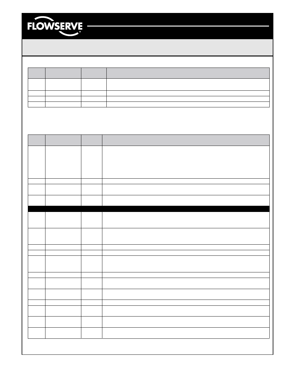
Appendix B. Discrete Output Block Parameters
The following table provides a list of all DO block parameters. Critical Factory Default values are highlighted.