Buswitch, With f, Oundation – Flowserve BUSwitch User Manual
Page 6: Adjustment of switch cams, Embedded software specifications
AXAIM020-01
(AUTO-48)
3/03
Page 6 of 16
© 2003, Flowserve Corporation, Printed in U.S.A.
BUSwitch
™
with F
OUNDATION
®
Fieldbus Protocol
Installation, Operating and Maintenance Instructions
Flowserve Corporation
1350 N. Mountain Springs Parkway
1978 Foreman Dr.
Flow Control Division
Springville, Utah 84663-3004
Cookeville, TN 38501
www.flowserve.com
Phone: 801 489 8611
Phone: 931 432 4021
Special Notes on the fieldbus cabling
Minimum voltage requirement for the BUSwitch
™
is 9.5 VDC supply. The output voltage of the fieldbus
power supply, the current drawn and the electrical
characteristics of the data cable determine the maxi-
mum distance that a particular segment can span.
With data cable that conforms to the FF cable type ‘A’
specification, distances of 1900 meters are guaran-
teed. If a shielded cable is used, connect the shield to
ground at one point only. Multiple grounds can lead
to ground loops which can impair the proper opera-
tion of the segment. For this reason, a shield connec-
tion has not been provided inside the BUSwitch
™
housing. Radio frequency grounding at multiple
points through the use of capacitors, allowed by
the FF protocols, can be used for increased high
frequency EMI (electromagnetic interference)
shielding. For a more thorough treatment of data
cable wiring and aspects of installation refer to the
F
OUNDATION
®
Fieldbus application guide AG-140:
Wiring and Installation 31.25 Kbit/s, Voltage Mode,
Wire Medium. Its reference section lists additional
documentation that can be consulted for further
information.
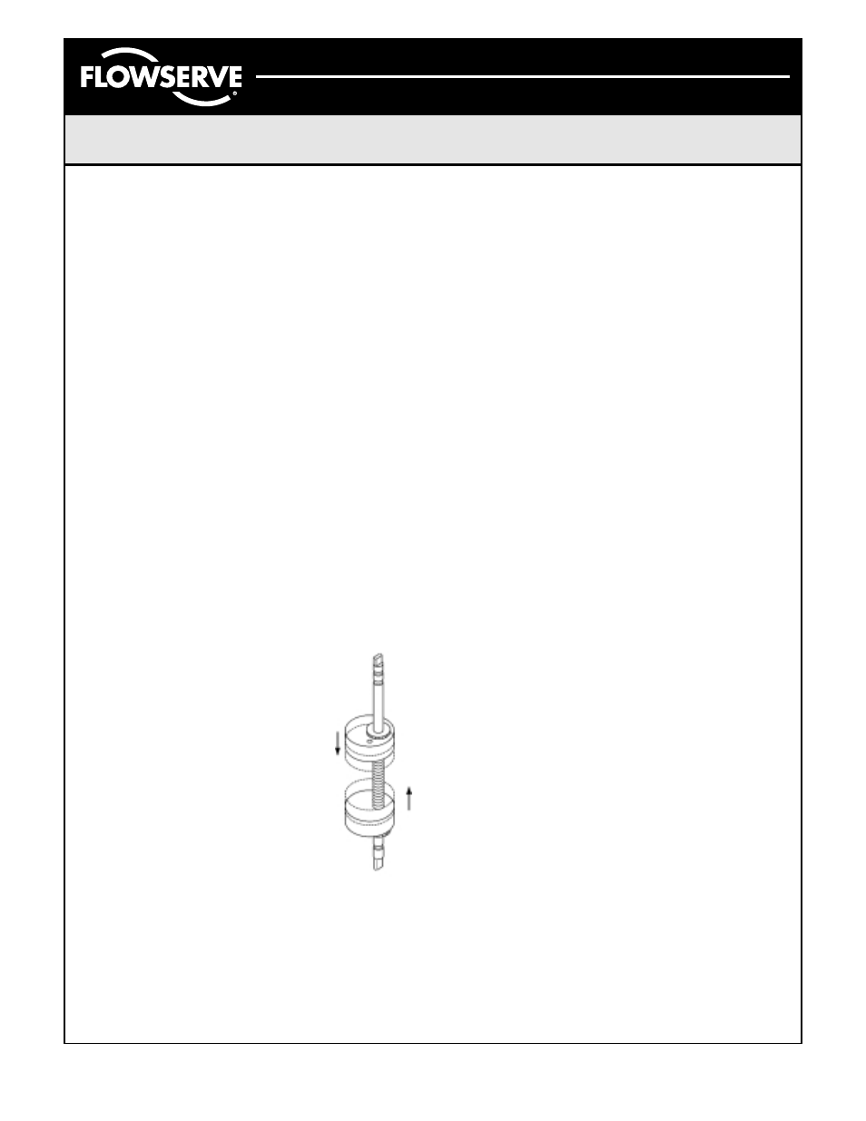
Adjustment of Switch Cams
1. Loosen five captive cover screws
and remove lid, turning slightly
while lifting.
2. Place the actuator in the clock-wise
(CW) position and connect to the
fieldbus segment.
3. Push down on the top cam until it
clears the splined coupler, rotating
clockwise until the CW LED is
illuminated (Figure 5).
4. Release the cam and insure that
it fully engages the spline.
5. Place the actuator in the counter-
clockwise (CCW) position.
6. Pull up on the lower cam until it clears its
splined coupler, rotating counter-clockwise
until the CCW LED is illuminated (Figure 5).
BUSwitch
™
Embedded Software
Specifications
Flowserve’s BUSwitch
™
utilizes the SMAR communi-
cations stack. Factory-configured embedded software
includes the resource block, transducer block,
(2) DO blocks and (2) DI blocks. The next sections
provide information about each of these blocks.
Flowserve assumes the reader has a fundamental
understanding of the nature, nomenclature, and
geometry of these blocks.
DISCLOSURE
The Flowserve BUSwitch
™
has been certified by
F
OUNDATION
®
Fieldbus (FF) to be interoperable
in accordance with FF standards. In addition, the
BUSwitch
™
device has been proven interoperable
with Fisher’s DeltaV Control System. The term
interoperable DOES NOT mean the BUSwitch
™
device will behave exactly like other FF-interoperable
devices. Because of some flexibility in the interpreta-
tion of FF standards, some minor differences exist
between many manufacturers. These differences
DO NOT affect the function of this device.
Flowserve has disclosed, in an addendum to this
document, known issues with individual control
systems we have tested. Users and systems
integrators should make allowances for these
issues. Flowserve will not be responsible for
modifying software to change the behavior of the
BUSwitch
™
relative to these issues.
Figure 5