Wiring prs 9 – Flowserve PRS 9 User Manual
Page 10
Advertising
10
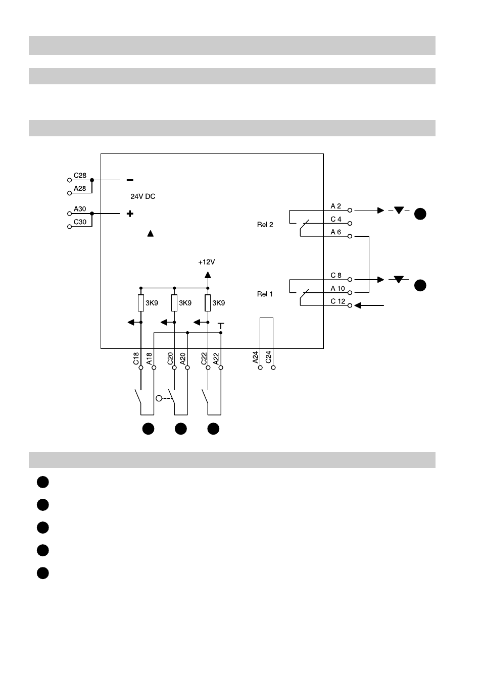
Key to wiring diagram
P2 Level switch NRS 2-4 or NRS 2-5 (24 V DC) from corresponding level electrode 2
Position-controlled limit switch of the drain valve
P1 Level switch NRS 2-4 or NRS 2-5 (24 V DC) from level electrode 1
Rel 2 for opening the drain valve
Rel 1 for closing the drain valve
Design “c” / “d”
Wiring diagram
Wiring is effected via the 32 pole screw-type connector.
1
1
Wiring
PRS 9
2
3
4
5
Fig. 3
2
3
4
5
Advertising
See also other documents in the category Flowserve Hardware:
- Tandem Seal (8 pages)
- 978 Chemiepac (12 pages)
- ISC2 Single Pusher Repair (8 pages)
- LS-300 Series Durametallic (4 pages)
- Pac-Seal Type 16 (8 pages)
- U Series BW Seals (4 pages)
- ISC2 Dual Pusher Repair (12 pages)
- ISC2 Single metal bellows seal (8 pages)
- Durametallic Double CRO (8 pages)
- VRA-C Series Durametallic (4 pages)
- ISC2 Dual metal bellows sea (12 pages)
- Single Inside Pusher Type Seal (8 pages)
- Bearing Gard (2 pages)
- X-200 (12 pages)
- GTS Series (12 pages)
- MSS Series (12 pages)
- SLC Series Interseal (12 pages)
- QB Series BW Seals (8 pages)
- SLM-6100 (12 pages)
- SLM-6200 (12 pages)
- High Temperature Metal Bellows Seals (8 pages)
- X Series BW Seals (8 pages)
- ML-200 Series Durametallic (8 pages)
- ML-200 Series Durametallic (8 pages)
- Circulator (12 pages)
- ISC Series (16 pages)
- Gas Barrier Control System (4 pages)
- CPM Series (8 pages)
- CPM Series (12 pages)
- Mechanical Seal and Seal Support System Storage (4 pages)
- RIS Seal (12 pages)
- 682 Seal Cooler (8 pages)
- ISC2 Series (8 pages)
- ISC2 Series (116 pages)
- Pac-Seal Type 52 (8 pages)
- Pac-Seal Type 31 (8 pages)
- ST Series (8 pages)
- Mechanical Seal General (16 pages)
- Dual Pressurized Seals (8 pages)
- Uniseal Series BW Seals (8 pages)
- XLC Series (8 pages)
- PSS II Durametallic (8 pages)
- PSS II (16 pages)
- ISC1SX (8 pages)
- ISC1PX (8 pages)