9 nmi and fnmi – Fluke Biomedical 960CI-200 User Manual
Page 14
Theory of Operation
4
4-4
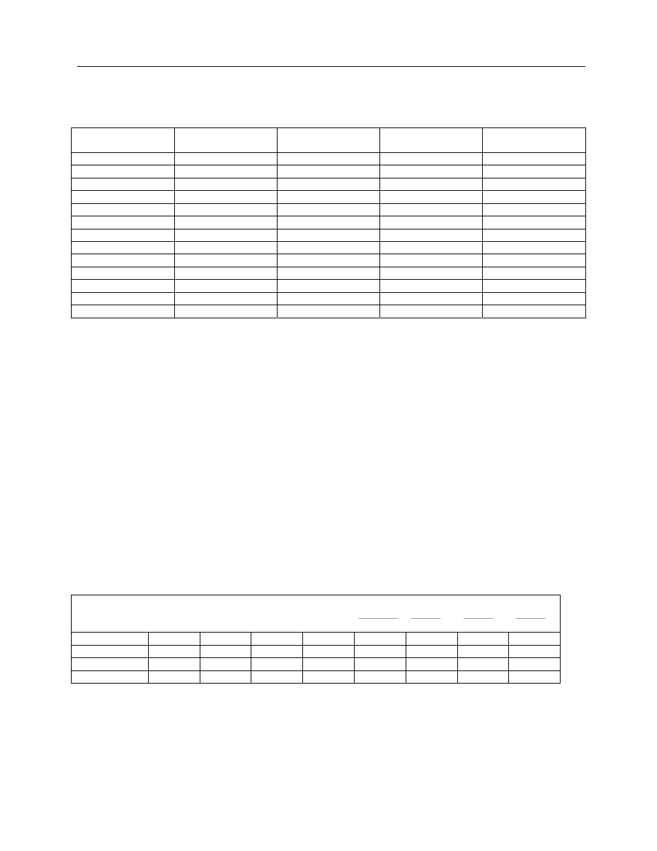
Table 4-2. Baud Rate Settings
SW2
(Baud Rate)
Pin 1 to 8
(S3)
Pin 2 to 7
(S2)
Pin 3 to 6
(S1)
Pin 4 to 5
(S0)
110.0
OP OP OP OP
150.0
OP OP OP CL
300.0
OP OP CL OP
2400.0
OP OP CL CL
1200.0 OP
CL
OP
OP
1800.0 OP
CL
OP
CL
4800.0 OP
CL
CL
OP
9600.0 OP
CL
CL
CL
600.0 CL
OP
OP
CL
50.0
CL CL OP CL
75.0
CL CL OP OP
200.0 CL
OP
CL
OP
134.5 CL
OP
CL
CL
NOTE: OP = Open CL = Closed
4.9 NMI and FNMI
Clock generator U13 is a CMOS programmable bit rate generator that gets 302700 Hz at its CP (pin 5) input and is set
with S0 = high, S1 = low, S2 = high, and S3 = low to generate a frequency output at pin 10 that is sent to dual decade
counter U14. U14 pin 7 has 4 Hz NMI, while pins 12 & 13 have 100 Hz FNMI.
4.10 Memory
The 960CI-200 Communications Isolator has 32K of memory using one 32K x 8 chip. One memory socket is used for a
PROM (address 8000 through FFFF) and three sockets are used for RAM memory (address 2000 through 7FFF). When
memory is accessed, U6 will have four chips enable signals (CE) on its output, depending on the address as shown in
table 4-3.
Table 4-3. Address Decoding For Memory
Address
A13
A12
A11
TYPE
Line
PROM
RAM 1
RAM 2
RAM 3
2000
–
3FFF
0 0 0 RAM
1 0 1 1
4000
–
5FFF
0 0 1 RAM
1 1 0 1
6000
–
7FFF
0 1 0 RAM
1 1 1 0
8000
–
FFFF
1 0 1 PROM
0 1 1 1
ICs U3, U4, U5 are RAM and U2 is PROM.