Chapter 2 installation instructions – Foxconn P4M800P7MA-ERS2 User Manual
Page 22
15
Chapter 2 Installation Instructions
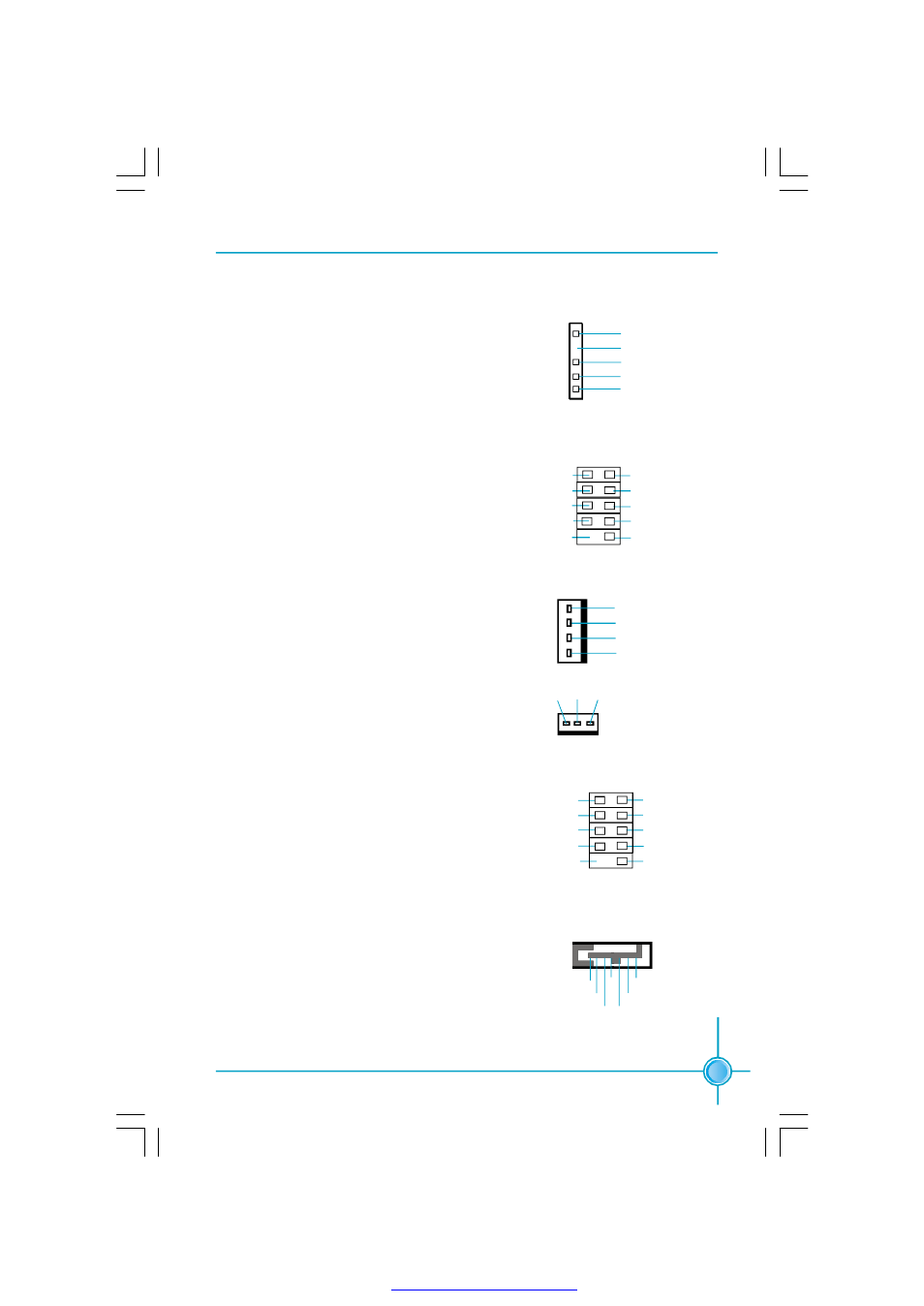
IrDA Header: IR (optional)
This connector supports wireless transmitting
and receiving device. Before using this function,
configure the settings of IR Address, IR Mode
and IR IRQ from the “Integrated Peripherals”
section of the CMOS Setup.
USB Headers: F_USB1, F_USB2
Besides four USB ports on the rear panel, the
series of motherboards also have two 10-pin
header on board which may connect to front
panel USB cable (optional) to provide addi-
tional four USB ports.
1
IR
+5V
GND
RX
T X
E m p t y
F_USB1/2
VCC
D+
D-
Empty
GND
NC
D+
D-
GND
VCC
Fan Connectors: CPU_FAN1, SYS_FAN1
The speed of CPU_FAN1 and SYS_FAN1 can
be detected and viewed in “PC Health Status”
section of the CMOS Setup. These fans will be
automatically turned off after the system enters
suspend mode.
CPU_FAN1
POWER
GROUND
CONTROL
S ENS E
1
SYS_FAN1
SENSE
+12V
GND
1
1394 Header: F_1394_1, F_1394_2 (optional)
The 1394 expansion cable can be connected to
either the front (provided that the front panel of
your chassis is equipped with the appropriate
interface) or real panel of the chassis.
TPA+
F_1394_1/2
10
9
GND
TP B+
+12V
Empty
2
1
GND
TPB-
+12V
TPA-
GND
S-ATA Connectors: SATA_1, SATA_2
The S-ATA connector is used to connect the S-
ATA device to the motherboard. These connec-
tors support the thin Serial ATA cables for pri-
mary storage devices. The current Serial ATA in-
terface allows up to 150MB/s data transfer rate.
1
SATA
_1/SATA _2
GND GND
GND
RX+
RX-
TX -
TX +
PDF 文件使用 "pdfFactory" 试用版本创建