10 pole zero and jitter compensation – GBS Elektronik MCA-527 User Manual
Page 36
MCA527
3.2.10 Pole Zero and Jitter Compensation
The pole zero correction is applied to make sure that a voltage step starting from the base
line is evaluated with the same amplitude as signal sitting on the falling slope of a
proceeding step. Without correction the slope is causing an error.
If the decay time constant of the signal is known, the slope can be easily calculated from
the amplitude. In practical terms pole zero correction is achieved by adding a defined
amount of DC from the input to the result. The pole zero value to be set is a value from
0...2499, for compatibility reasons the same as with MCA166. This value is proportional to
the amount of DC added for correction. It is reciprocal connected with the decay time
constant by:
For pole zero adjustment, go to the pole zero settings window of the software. There the
spectroscopical filter is applied to the signal before and after a voltage step, but where the
result should be zero. The difference between those both measurements is the pole zero
offset and the results are averaged over 0.8s. The pole zero value has now to be adjusted
such that the pole zero offset becomes zero.
Jitter is a typical problem of digital MCA and it is caused by the fact that registered events
are asynchronous to the ADC sample clock. Therefore the timing of the spectroscopical
filter is always inaccurate by around 100ns. Assuming a decay time constant of 50µs, an
inaccuracy of 100ns can may cause an error of 100ns/50µs=0.2%. This is unacceptable
high for good spectroscopy. With some minor modifications the spectroscopical filter can
36
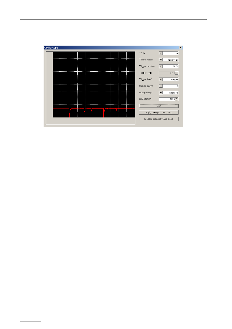
Figure 18: Wrong offset setting. The offset setting for negative signals should be at 90%
and not at 14% as shown here. So it is not possible to measure high amplitude
signals as they are cut off.
t=
88650µs
PZC