GBS Elektronik MCA166-USB Behavior at different Temperatures User Manual
Page 5
factor 2 period. At the gain of 15 and the gain of 30 this oscillation is disturbed. This can be explained by
additional attenuators which are switched at these gains.
The results also seem to be reproducible within 100 ppm/°C between different MCAs. But this was not further
examined as these measurements are quite time consuming.
5. Temperature drift of detectors
For practical purposes, it is useless to look only at the MCA drift; the drift of detectors have always to be taken
into account. For this experiment, a CZT 500 detector was warmed up from -5°C to 22°C and a HPGe was
cooled down from 22°C to 12°C.
-20
-10
0
10
20
30
40
50
T im e (m inutes)
0.98
0.99
1
1.01
re
la
ti
v
e
p
e
a
k
s
h
if
t
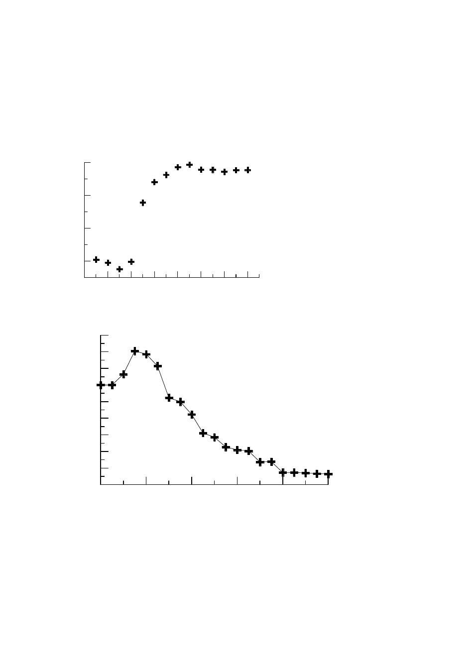
C Z T 500 d etecto r w arm in g u p
fro m -5°C to +22°C
Fig. 5. The thermal time constant of a small CZT 500 is in the order of 5 minutes. The peak drift is about 1E-3
/°C
0
2 0
4 0
6 0
8 0
1 0 0
T im e (m in u te s)
0 .9 9 8 8
0 .9 9 9
0 .9 9 9 2
0 .9 9 9 4
0 .9 9 9 6
0 .9 9 9 8
1
1 .0 0 0 2
1 .0 0 0 4
1 .0 0 0 6
re
la
ti
v
e
p
e
a
k
s
h
if
t
P e a k sh ift o f th e C o 6 0 1 3 3 3 ke V P e a k w he n
th e d e te cto r (G L 0 3 1 0 ) is c o o le d d o w n fro m
2 2 °C to 1 2 °C . T h e M C A is k e p t a t c o n s ta n t
te m p e ra tu re . M C A g a in : 5 *0 .6 , 2 µ s sh a pin g tim e .
Tem perature coefficent
detector: ~1E-4/°C
Fig. 6. The time constant of a planar HPGe detector is around 25 minutes. The drift is about 1E-4 /°C
It can be seen that the time constant of a CdZnTe detector is quite short, which corresponds to its small size. The
thermal time constant of a HPGe detector is comparable to that of the MCA, and the drift is small, but not
negligible. It has to be mentioned that the drift of a HPGe is always the drift of its preamp, as the detection
crystal is always at liquid nitrogen temperature.
6. Stabilisation
If for a certain measurement task, a well known peak is always present, then the method of peak stabilization can
be applied to compensate peak drift regardless if caused by the detector or by the MCA. For stabilization, the
reference peak has to be marked with a special stabilization ROI. The centroid of this ROI is evaluated
periodically and the gain is adjusted correspondingly.