GBS Elektronik MCA166-USB Behavior at different Temperatures User Manual
Page 6
0
3 0
6 0
90
1 20
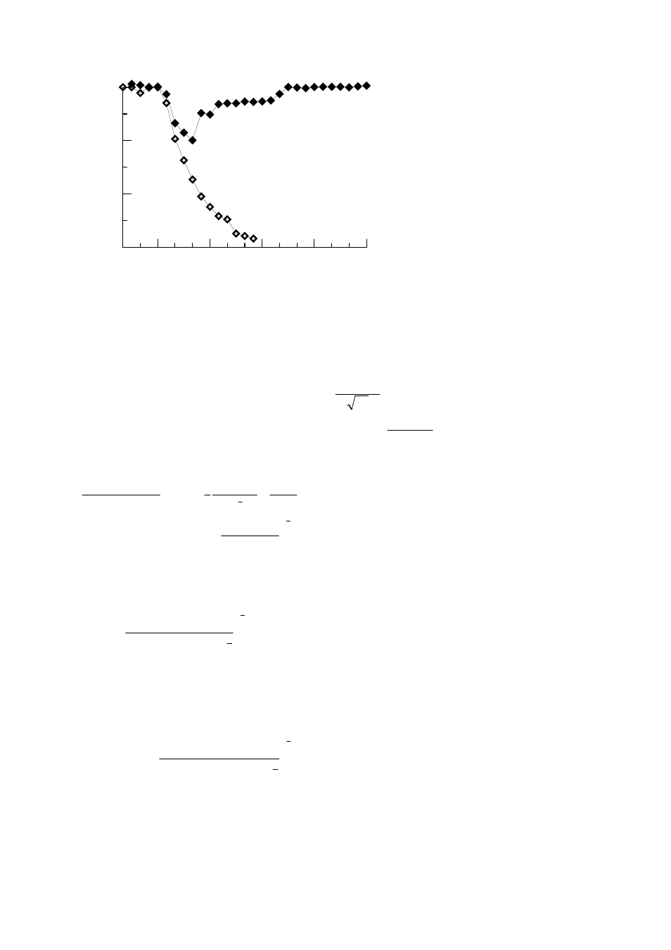
T im e (m in )
0 .99 4
0 .9 96
0.99 8
1
D
ri
ft
(
re
la
ti
v
e
)
w ith sta b iliza tio n
w ith o ut stab iliza tio n
Fig. 7. Peak drift of the MCA166 with detector GL0310 and a gain of 2.8 when exposed to a sudden temperature
change of 10°C, with and without stabilization.
The period of stabilization is determined for the MCA166 by the counts in the ROI. Default is at the moment a
stabilization cycle every 25000 counts, only in newer versions of WinSpec this area can be adjusted.
The stabilization cycle time is something which can be optimized. If the stabilization cycle time is too long, then
the drift may be faster and may not be fully compensated. If the stabilization cycle time is too short, then the error
of centroid evaluation acts as spectrum broadening noise and adds to the FWHM. The centroid evaluation error
depending on FWHM and area N is assumed as:
∆
E
FWHM
N
c
=
(4)
The centroid drift within a stabilization cycle is:
∆
E
E
t
E
N
n
D
= ⋅ ⋅ = ⋅ ⋅
ϑ
ϑ
✁
(5)
with the gain drift rate
ϑ
, the stabilisation peak photon energy E and the stabilization peak count rate
✁
n
. An
optimum can be found where the sum of both contributions is minimized.
(
)
d
E
E
dN
FWHM
N
E
n
c
D
∆
∆
+
= = −
+ ⋅
0
1
2
3
2
ϑ
✁
(6)
This leads to an area
N
FWHM n
E
opt
=
⋅
⋅ ⋅
✁
2
2
3
ϑ
(7)
Examples:
-For the example of Fig. 7 a maximum drift rate of 4 ppm/s can be assumed. For stabilization a peak at 352 keV
with a FWHM of 1 keV and a peak area count rate of 52 cps is used. So the optimum stabilization area is
N
keV
cps
keV
opt
s
=
⋅
⋅
⋅ ⋅
=
−
1
52
2 352
4 10
700
6 1
2
3
This means that a stabilisation cycle here is 13s and a 4% peak broadening due to centroid calculation error has
to be accepted.
-A HPGe is to be stabilized on the weak K40 1460 keV peak for environmental measurements. FWHM at 1460
keV is 2 keV and a peak count rate of 0.4 cps can be assumed. As drift rate the maximum drift rate immediately
after switching on (1.6 ppm/s, same as a temperature change of 5°C) is assumed. Here, an optimum stabilization
area of
N
keV
cps
keV
opt
s
=
⋅
⋅
⋅ ⋅
=
−
2
0 4
2 1460
1 6 10
30
6 1
2
3
.
.
is calculated. This is near the lower limit for detection of the peak. Areas lower than 30 should not be used at all.
Here, the stabilization time is 125s and a peak broadening of 18% has to be accepted.
-For U235 enrichment measurement with a NaI, the 186 keV peak used for stabilization. FWHM there is 22 keV,
the peak rate is assumed with 1400cps and the NaI is considered ten times less stable than the MCA (16 ppm/s).
In this case, the optimum area calculates as: