Hypertherm DuraChill 5 HP Air-Cooled Chiller For Hypertherm User Manual
Page 6
- 6 -
2.2.1 Control
System
This system controls and monitors Chiller operation. It consists of a microprocessor-based controller linked to the
various sensors, gauges, valves, switches, and signal input/output connections on the unit.
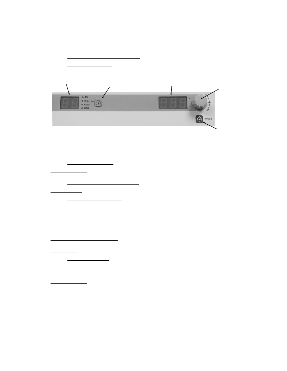
Control Panel — Temperature set point, temperature units, and other operating parameters are set via the Control
Panel. Operating information is displayed on a local LED readout.
TEMPERATURE CONTROLLER PCB = Part No.: 500-367
POWER SUPPLY PCB = Part No.: 215-513
Power Switch / Disconnect — The main power switch is located on the front door of the unit. This switch also
functions as a power disconnect when access to the unit’s electrical components and terminal blocks is required; the
access door cannot be opened until the Power Switch / Disconnect is placed in the Off position.
DISCONNECT SWITCH = Part No.: 215-629
Temperature Probe — An internal RTD is used to measure fluid temperature downstream of the pump. Its reading is
displayed on the Control Panel LED.
PLATINUM TEMPERATURE PROBE = Part No.: 200-450
Pressure Sensor — Measures fluid pressure at the outlet of the Chiller.
PRESSURE TRANSDUCER = Part No.: 750-757
2.2.2
Fluid Circulation System
This system governs the circulation of fluid through the unit.
Reservoir Tank — This polyethylene tank is used to maintain stable temperature control and an adequate reserve of
fluid for the system. It is equipped with a float switch that monitors fluid level and activates an alarm if the level drops
too low.
Tank Sight Glass or Level Indicator — This indicator serves as a convenient means of checking the liquid level within
the Reservoir Tank.
Process Pump — The high pressure turbine pump is used to pump fluid from the Reservoir Tank to the process.
1HP TURBINE PUMP
200-240/380-460V 50/60Hz = Part No.: 505-174
575-600V 60Hz = Part No.: 505-178
Recirculation Pump — The stainless steel centrifugal pump assures adequate flow through the evaporator to optimize
heat transfer.
½ HP CENTRIFUGAL PUMP
200-240/380-460V 50/60HZ = Part No.: 505-175
575-600V 60HZ = Part No.: 505-177
Units/Menu
Select Button
Select/Set Knob
Power Button
Pressure/Flow Display
Temperature Display