System tests, Test 1 – voltage input, System tests -18 – Hypertherm Powermax45 Service Manual User Manual
Page 94: Test 1 – voltage input -18, Test 1 – voltage, Perform test 1 – voltage, Powermax
TroubleshooTing and sysTem TesTs
5-18
powermax
45
Service Manual
System tests
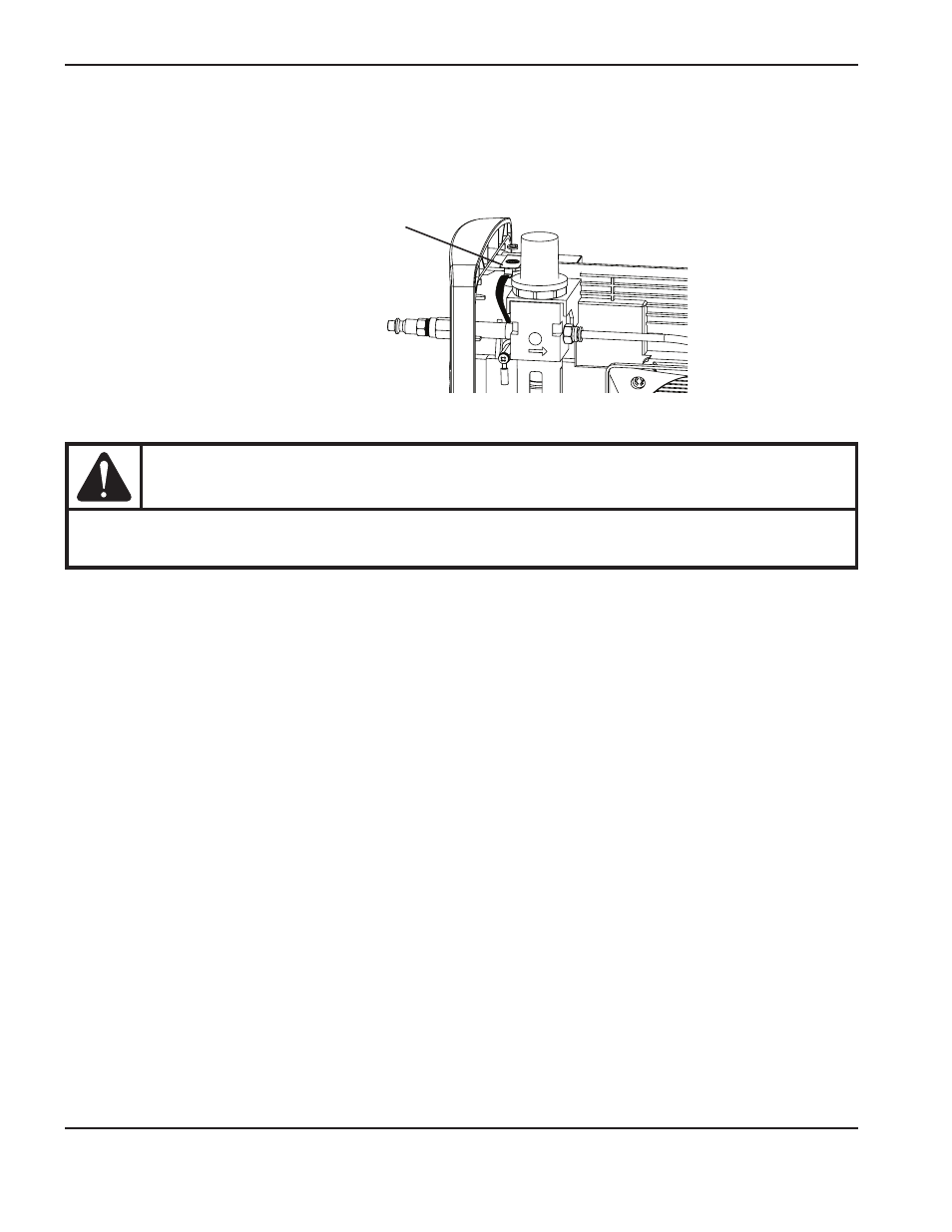
There is a ground clip near the top of the rear end cap that can be used as ground for any tests that require the
multimeter to be attached to ground. There is also a ground on the heat sink with access next to the power board and
below the power switch.
WARNINg
Voltages of up to 50 VdC continue to be present on the dC bus for at least 30 seconds after
disconnecting the input power. Allow bus voltages to dissipate before performing any tests.
Test 1 – voltage input
Check the incoming voltage and the line voltage to the top of the power switch (S1).
1. Disconnect the electrical power and set the ON/OFF switch to OFF (O).
2. Once you have your test leads in place, reconnect the electrical power. Leave the ON/OFF switch set to OFF. The
voltage should equal the line voltage of the incoming circuit.
3. If the AC voltage is incorrect, check to see that you have power to the unit. If you do have power, check the power
cord for damage.
4. With the electrical power connected, set the ON/OFF switch to ON (I), and measure the AC voltage from J1 to J2
(labeled “AC” on the power board). This value should be the same as the incoming line voltage. If it is not, check
the ON/OFF switch.
whether the power board or the control board is faulty.
Note: All values can be ±15%.
Ground wire clip