J1: digital i/o connector (4 in, 4 out), J3: audio front header, J5: usb4/usb5 connector – IBASE MB900 User Manual
Page 22: J6: usb6/usb7 connector
Advertising
INSTALLATIONS
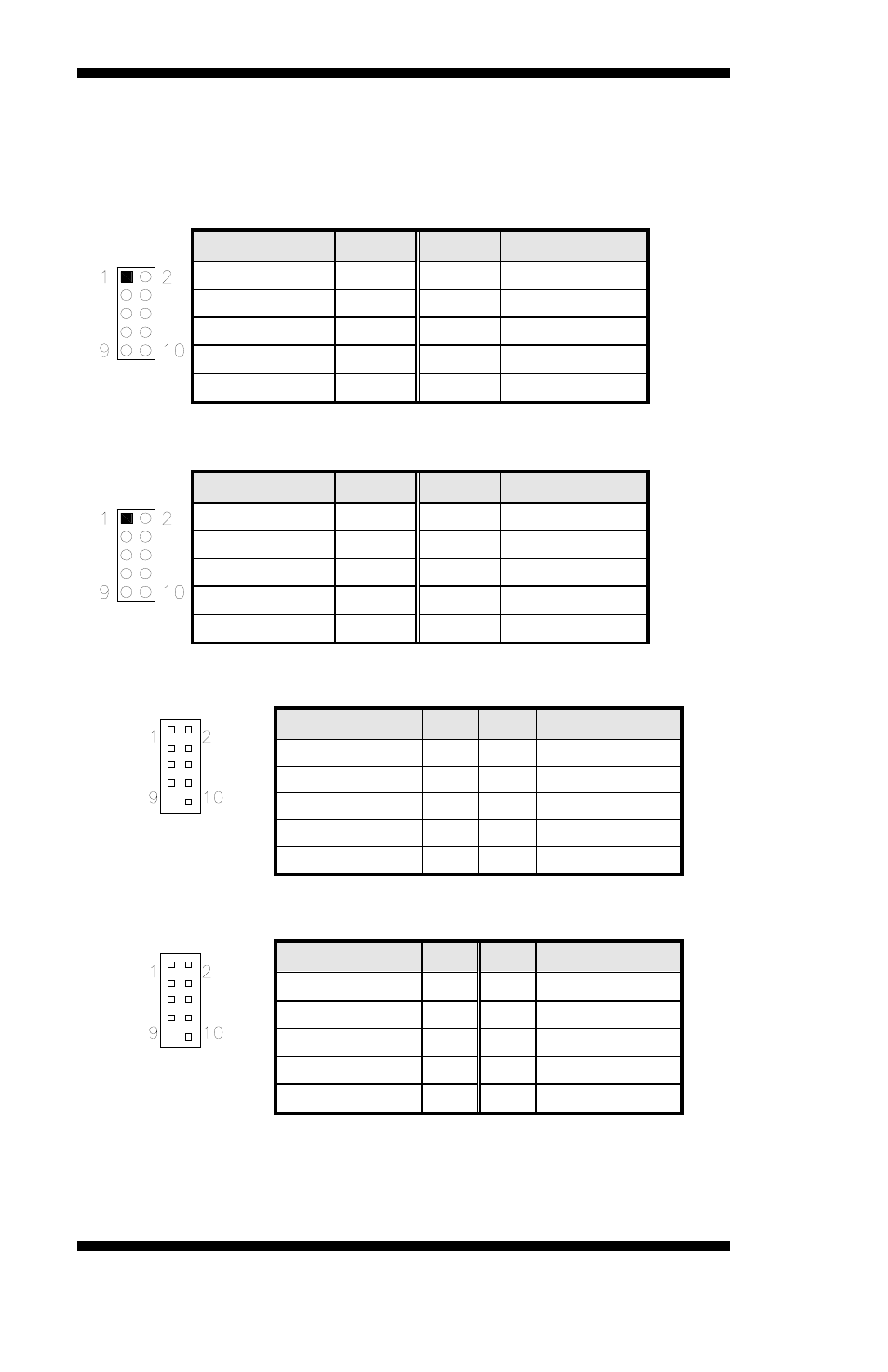
J1: Digital I/O Connector (4 in, 4 out)
This 10-pin digital I/O connector supports TTL levels and is used to
control external devices requiring ON/OFF circuitry.
Signal Name
Pin #
Pin #
Signal Name
Ground 1 2 +5V
Out3 3
4 Out1
Out2 5
6 Out0
IN3 7
8 IN1
IN2 9
10 IN0
J3: Audio Front Header
Signal Name
Pin #
Pin #
Signal Name
MIC2_L 1 2 Ground
MIC2_R 3 4 Presence#
Line2_L 5 6 MIC2_ID
Sense 7 8 NC
Line2_R 9 10 Line2_ID
J5: USB4/USB5 Connector
Signal Name
Pin
Pin Signal Name
Vcc 1
2 Vcc
D- 3
4 D-
D+ 5
6 D+
Ground 7
8 Ground
Protect
Pin
9
10
NC
J6: USB6/USB7 Connector
Signal Name
Pin
Pin Signal Name
Vcc 1
2 Vcc
D- 3
4 D-
D+ 5
6 D+
Ground 7
8 Ground
Protect
Pin
9
10
NC
18
MB900-R User’s Manual
Advertising