Fan2, fan3, fan4: fan power connectors, Ide1: primary ide connectors, Pcie_1: x16 pci express slot – IBASE MB900 User Manual
Page 24: Pcie_2: x1 pci express slot, Pci1, pci5: pci slots, Cn12: cf socket, J12: smbus
INSTALLATIONS
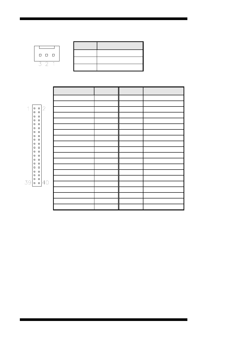
FAN2, FAN3, FAN4: Fan Power Connectors
Pin #
Signal Name
1 Ground
2 +12V
3 Rotation
detection
IDE1: Primary IDE Connectors
IDE1
Signal Name
Pin #
Pin #
Signal Name
Reset IDE
1
2
Ground
Host data 7
3
4
Host data 8
Host data 6
5
6
Host data 9
Host data 5
7
8
Host data 10
Host data 4
9
10
Host data 11
Host data 3
11
12
Host data 12
Host data 2
13
14
Host data 13
Host data 1
15
16
Host data 14
Host data 0
17
18
Host data 15
Ground
19
20 Protect
pin
DRQ0
21
22 Ground
Host IOW
23
24
Ground
Host IOR
25
26
Ground
IOCHRDY
27
28 Host
ALE
DACK0
29
30 Ground
IRQ14
31
32
No connect
Address 1
33
34
No connect
Address 0
35
36
Address 2
Chip select 0
37
38
Chip select 1
Activity
39
40 Ground
PCIE_1: x16 PCI Express Slot
PCIE_2: x1 PCI Express Slot
PCI1, PCI5: PCI Slots
CN12: CF Socket
J12: SMBus
This is a 2-pin header. Pin 1 is SMB_CLK; Pin 2 is SMB_DATA.
20
MB900-R User’s Manual