Jp1: clear cmos setting, Jp2: lvds vdd select (5v / 3.3v), Jp3: hdd led pin header – IBASE IB530 User Manual
Page 13: Jp4: cf connector master/slave setting, Jp5, jp6: com3,4 rs232 +5v/+12v power setting, Normal (default), 5v jp3: hdd led pin header, Jp4 setting function, Short/closed master, Jp5, jp6 setting function
Advertising
INSTALLATIONS
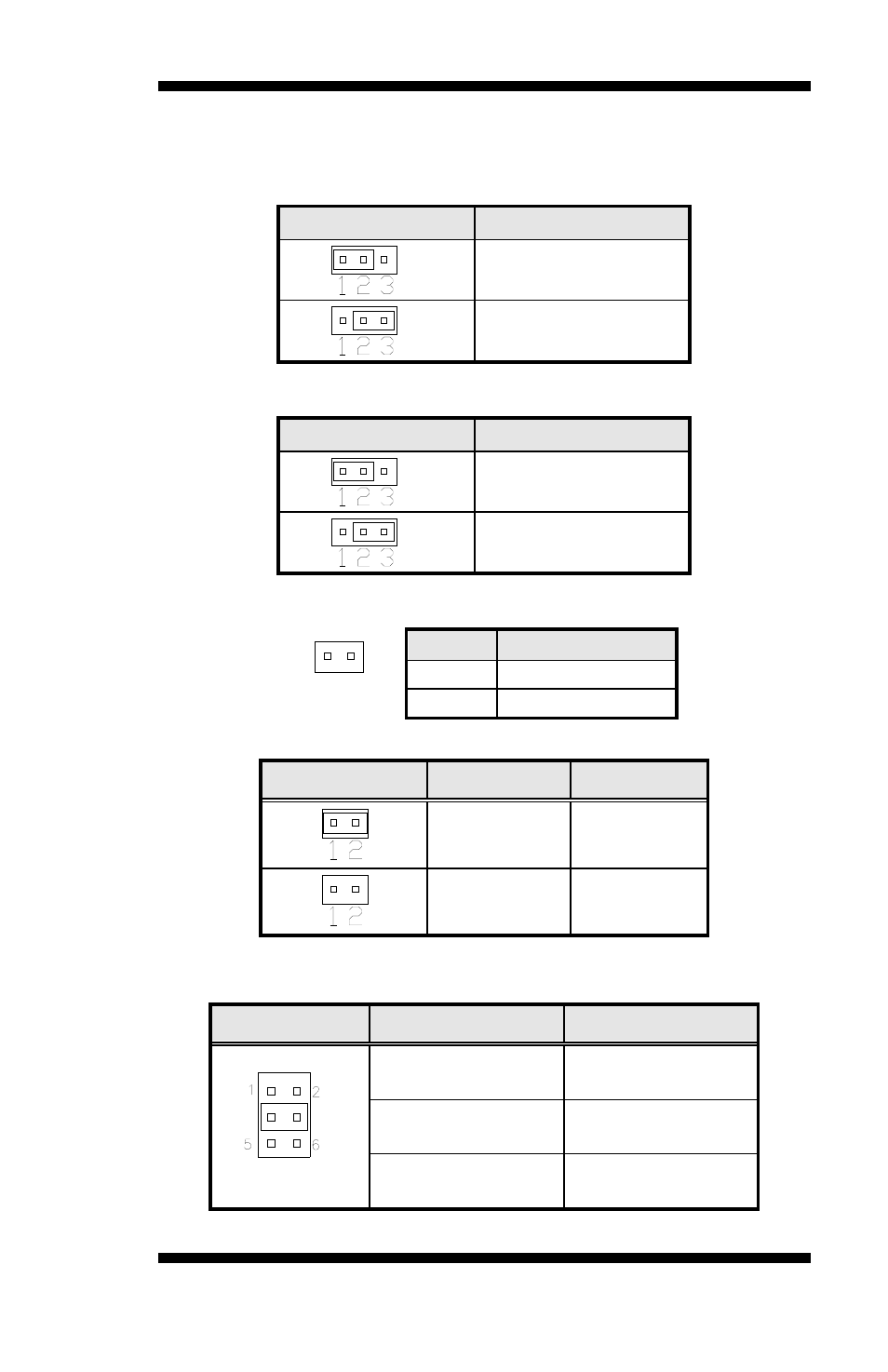
JP1: Clear CMOS Setting
Use JP1 to clear the CMOS contents. Note that the power connector
should be disconnected from the board before clearing CMOS.
JP1
Function
Normal (default)
Clear CMOS
JP2: LVDS VDD Select (5V / 3.3V)
JP2
VDD Setting
3.3V
5V
JP3: HDD LED Pin Header
Pin #
Signal Name
1 VCC
2
HDD_LED-
JP4: CF Connector master/Slave Setting
JP4
Setting
Function
Short/Closed
Master
Open Slave
JP5, JP6: COM3,4 RS232 +5V/+12V Power Setting
JP5, JP6
Setting
Function
Pin 1-2
Short/Closed
+12V
Pin 3-4
Short/Closed
Normal
Pin 5-6
Short/Closed
+5V
IB530F User’s Manual
9
Advertising