J2: reset switch, J4: external audio connector, J5: tft panel connector – IBASE IB530 User Manual
Page 19
INSTALLATIONS
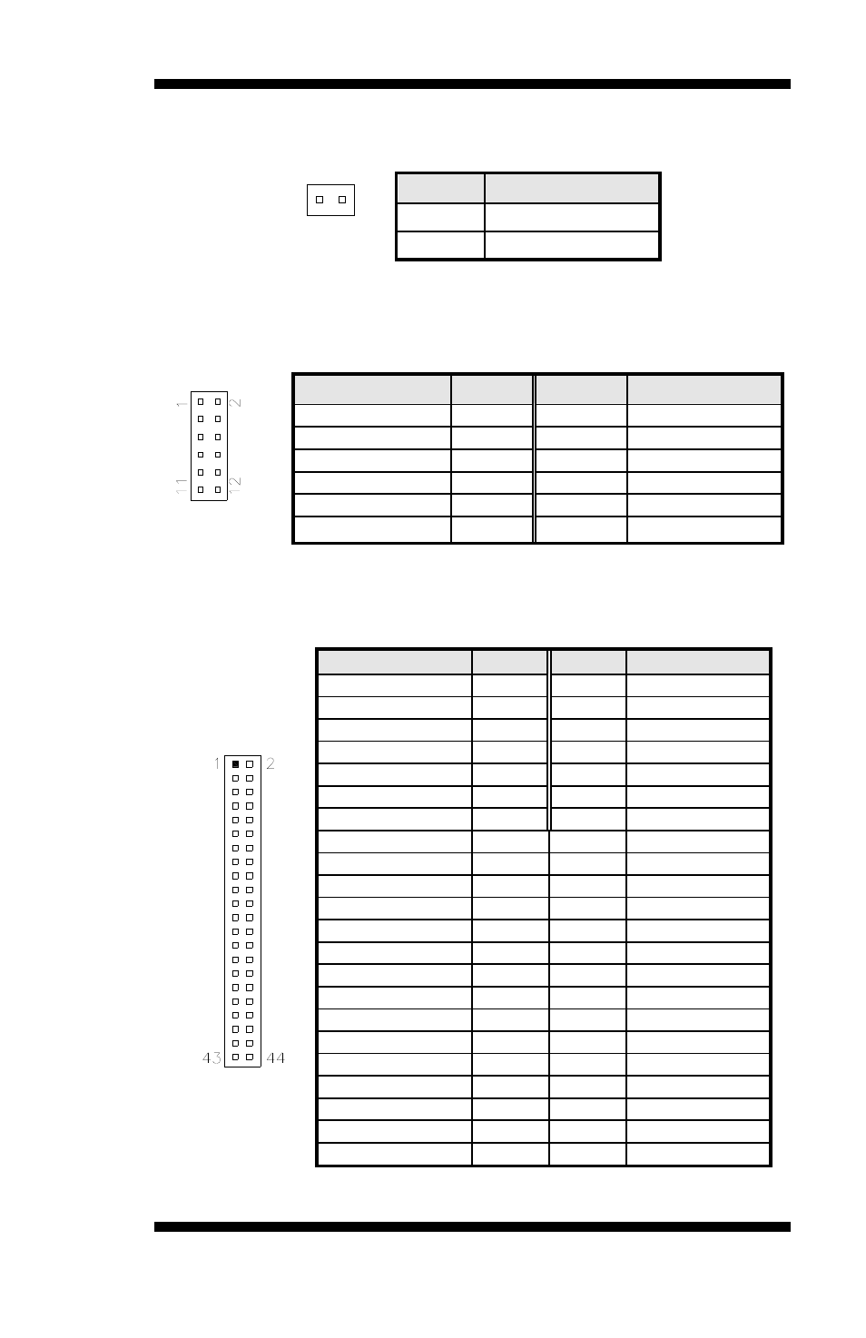
J2: Reset Switch
Pin #
Signal Name
1 Reset
2
Ground
J4: External Audio Connector
J4 is a 12-pin header that is used to connect to the optional audio cable
card that integrates jacks for Line In, Line Out and Mic.
Signal Name
Pin #
Pin #
Signal Name
LINEOUT R
1
2
LINEOUT L
Ground
3
4
Ground
LINEIN R
5
6
LINEIN L
Ground
7
8
Ground
Mic-In
9
10
VREFOUT
Ground
11 12
Protect
pin
J5: TFT Panel Connector (when board supports 24-bit)
Here is the pin definition of J5 when it supports for 24-bit TFT flat panel
LCD displays.
Signal Name
Pin #
Pin #
Signal Name
+12V 1
2 +12V
Ground 3
4 Ground
5V/3.3V 5
6 5V/3.3V
N.C. 7
8
Ground
R0 9
10
R1
R2 11
12 R3
R4 13
14 R5
R6 15
16 R7
G0 17
18 G1
G2 19
20 G3
G4 21
22 G5
G6 23
24 G7
B0 25
26 B1
B2 27
28 B3
B4 29
30 B5
B6 31
32 B7
Ground 33
34 Ground
SHFCLK 35
36
FLM(VSYNC)
DISPENA(MDE)
37 38 LP(HSYNC)
Ground 39
40
ENABKL
Ground 41
42 N.C.
ENAVDD 43
44 5V/3.3V
*Depends on JP2 setting (1-2 for 3.3V / default, 2-3 for 5V).
IB530F User’s Manual
15