IBASE IB815 User Manual
Page 18
Advertising
INSTALLATIONS
14
IB815 User’s Manual
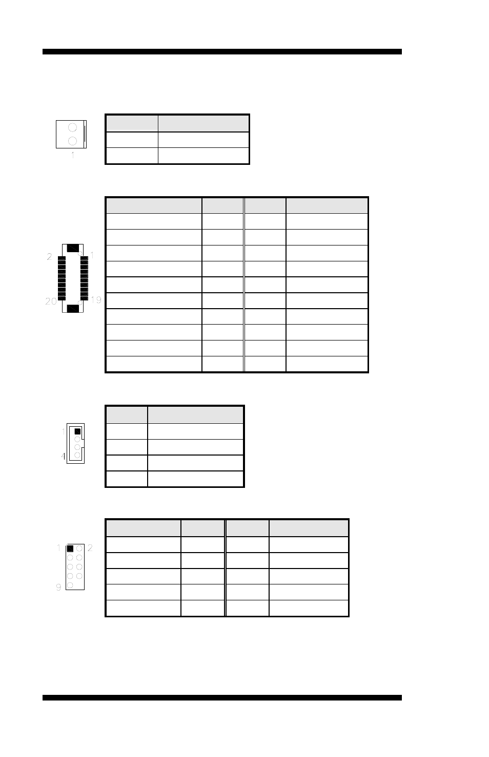
J7: AT_12V Connector
J7 is a DC-in internal connector supporting +12V.
Remarks: J7 and J6 connectors cannot be connected at the same time.
Pin #
Signal Name
1
+12V
2
GND
J8: LVDS Port (24bit)
Signal Name
Pin #
Pin #
Signal Name
D0_TX
1
2
D0_TX#
GND
3
4
GND
D1_TX
5
6
D1_TX#
GND
7
8
VDD1
D3_TX
9
10
D3_TX#
D2_TX
11
12
D2_TX#
GND
13
14
GND
CLK_TX
15
16
CLK_TX#
LVDS_BLON-
17
18
VDD1
SPC
19
20
SPD
J9: LVDS Backlight Connector
Pin #
Signal Name
1
+12V
2
Backlight Enable
3
ADJ
4
GND
JP10: PS/2 Keyboard and PS/2 Mouse Connectors
Signal Name Pin #
Pin #
Signal Name
GND
1
2
GND
5V
3
4
5V
MDA
5
6
KBDA
MCL
7
8
KBCL
NC
9
Advertising