IBASE IP402 User Manual
Page 16
INSTALLATIONS
12
IP402 User’s Manual
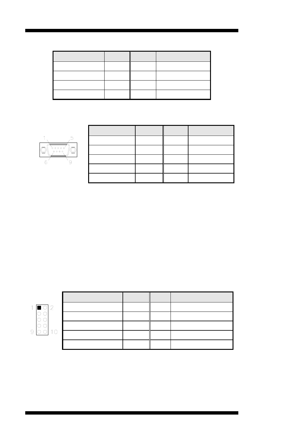
J2: PS/2 Keyboard and PS/2 Mouse Connectors
Signal Name
Pin #
Pin #
Signal Name
5V
1
2
5V
Mouse data
3
4
Keyboard data
Mouse clock
5
6
Keyboard clock
GND
7
8
GND
CN1A, CN1B: COM1(UP) and COM2(DOWN) Connector
COM1
Signal Name
Pin #
Pin # Signal Name
DCD
1
6
DSR
RXD
2
7
RTS
TXD
3
8
CTS
DTR
4
9
RI
GND
5
10
Not Used
CN4A, CN4B: VGA(UP) and DVI(DOWN) Connector
CN12: GbE_1 RJ-45 and USB2/3 Ports
CN15: DP and USB0/1 Ports
CN11: Audio Connector
The audio connector, from top to bottom, is composed of Line in, Line
out and Microphone jacks.
J13: Audio Pin Header for Chassis Front Panel
Signal Name
Pin
Pin
Signal Name
MIC IN_L
1
2
Ground
MIC IN_R
3
4
DET
LINE_R
5
6
Ground
Sense
7
8
KEY
LINE_L
9
10
Ground