IBASE IP402 User Manual
Page 19
Advertising
INSTALLATIONS
IP402 User’s Manual
15
JP13: SPDIF In/Out Connector
Pin #
Signal Name
1
SPDIF IN
2
Ground
3
SPDIF OUT
4
Ground
J7: Digital I/O
Signal Name Pin Pin
Signal Name
GND
1
2
VCC
OUT3
3
4
OUT1
OUT2
5
6
OUT0
IN3
7
8
IN1
IN2
9
10
IN0
J3: System Function Connector
J3 provides connectors for system indicators that provide light indication
of the computer activities and switches to change the computer status. J3
is a 8-pin header that provides interfaces for the following functions.
Signal Name
Pin #
Pin #
Signal Name
Power BTN
1
2
Power BTN
HDD LED+
3
4
HDD LED-
Reset BTN
5
6
Reset BTN
Power LED+
7
8
Power LED-
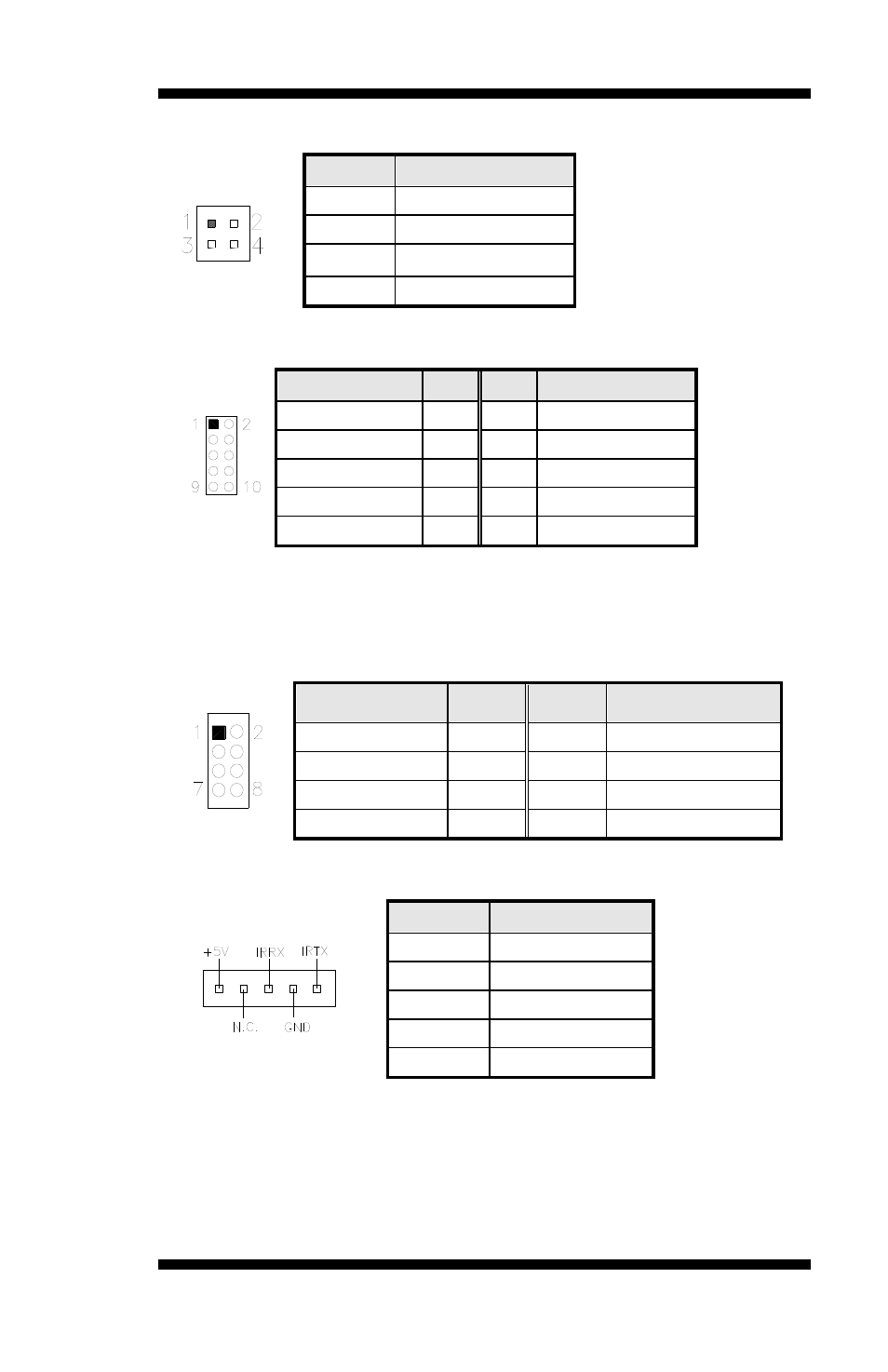
J1: IrDA Connector
Pin #
Signal Name
1
+5V
2
No connect
3
Ir RX
4
Ground
5
Ir TX
Advertising