Installations – IBASE IB704 User Manual
Page 16
Advertising
INSTALLATIONS
12
IB704 User’s Manual
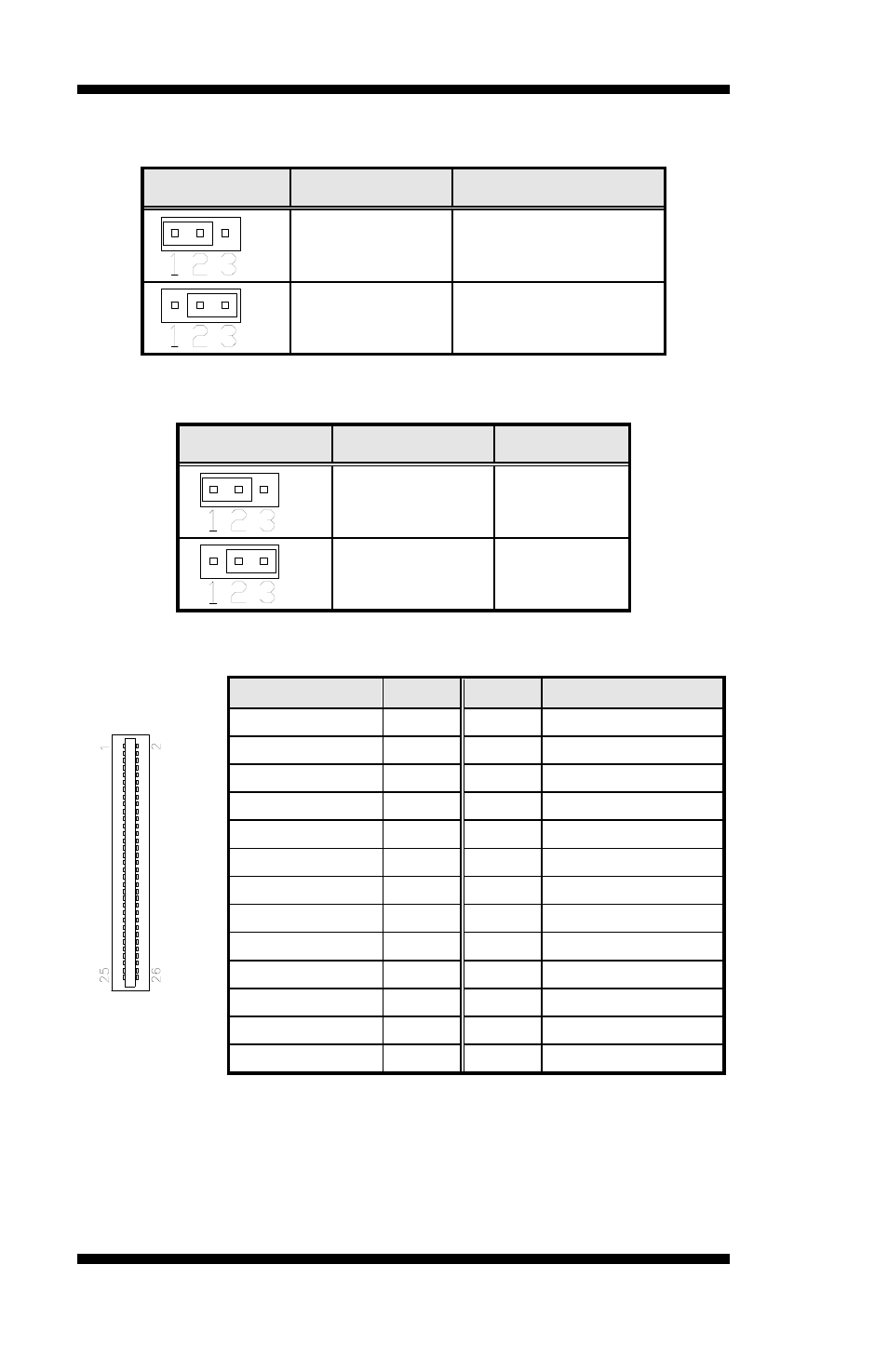
JP1: Clear CMOS Content
JP1
Setting
Function
Pin 1-2
Short/Closed
Normal Operation
Pin 2-3
Short/Closed
Clear CMOS Content
JP2: Panel Power Setting
JP2
Setting
Function
Pin 1-2
Short/Closed
+5V
Pin 2-3
Short/Closed
+3.3V
FDD1: Floppy Drive Connector
Signal Name
Pin #
Pin #
Signal Name
VCC
1
2
INDEX
VCC
3
4
DRV_SEL
VCC
5
6
DSK_CH
NC
7
8
NC
NC
9
10
MOTOR
DINST
11
12
DIR
NC
13
14
STEP
GND
15
16
WDATA
GND
17
18
EGATE
GND
19
20
TRACK
NC
21
22
WPROT
GND
23
24
RDATA
GND
25
26
SIDE
Advertising