IBASE IPPC1501-RE User Manual
Page 23
Advertising
Copyright © 2013 IBASE Technology Inc. All Rights Reserved.
15
IBASE Technology Inc.
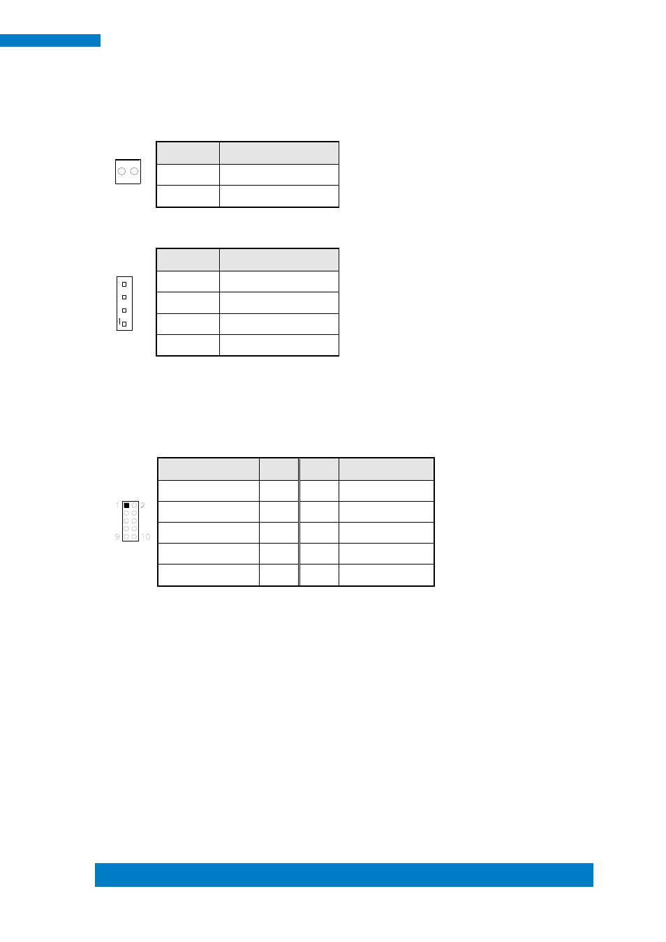
J1: Board Input Power Connector
1
Pin #
Signal Name
1
+12V to +24V
2
GND
J2, J3: SATA HDD Power Connector
Pin #
Signal Name
1
+5V
2
Ground
3
Ground
4
+12V
J4: Debug 80 Port Connector (factory use only)
J5: Digital I/O Connector
Signal Name
Pin
Pin
Signal Name
GND
1
2
VCC
OUT3
3
4
OUT1
OUT2
5
6
OUT0
IN3
7
8
IN1
IN2
9
10
IN0
J6: SPI Flash Connector (factory use only)
Advertising