IBASE IPPC1501-RE User Manual
Page 24
Advertising
16
IPPC1501-RE User Manual
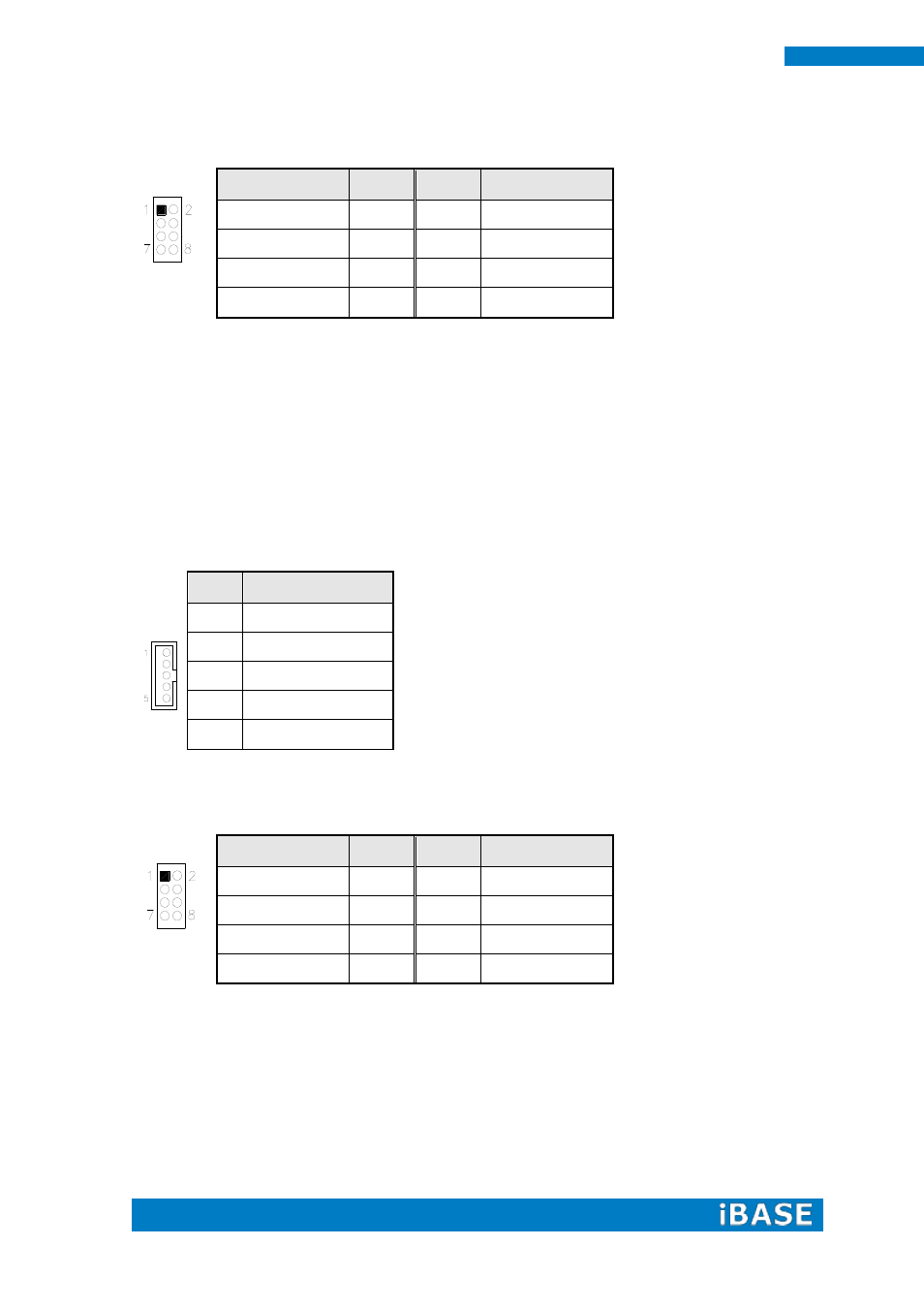
J7: Keyboard & Mouse Connector (DF11 Connector)
Signal Name
Pin #
Pin #
Signal Name
VCC
1
2
VCC
MDA
3
4
KBDA
MCL
5
6
KBCL
Ground
7
8
Ground
J8: DDR3 SO-DIMM Socket
J9: Mini PCIE Connector(Support mSATA)
J9 also supports mSATA. However, when J9 is used for mSATA, then CN3 SATA port cannot
be used. Only one of them can be used at one time to support SATA.
J11: Smart Battery Interface Connector
Pin #
Signal Name
1
RST
2
EXTSMI
3
Ground
4
DATA
5
CLK
J12, J13: USB3/4/5/6/7/8 Connector
Signal Name
Pin #
Pin #
Signal Name
Vcc
1
2
Ground
D-
3
4
D+
D+
5
6
D-
Ground
7
8
Vcc
J14: MCU Flash Connector (factory use only)
Advertising