Board dimensions – IBASE IPPCXXA9-RE User Manual
Page 24
16
IPPCxxA9-RE User Manual
Onboard
Button/Switch
1x power button
Watchdog Timer
Yes (256 segments, 0, 1, 2…255 sec/min)
Power
management
MSP430G2433
Power Connector
Standard ATX connector for AT (default)/ATX mode
RoHS
Yes
Golden Finger
A. PCIE(x16) golden finger x 1 for connecting to IP931
which has the following signals:
- PCIe(1x) x1, PCI x3 (via ITE IT8892)
- COM(TTL) x 1, USB 2.0 x 1
- 12V 2A power, 5V 2A, 3.3V 2A
**Each pin for PCI-express is 1A**
PCIE (8x) x2 For ID912
Golden finger A:
- COM(TTL) x 1, USB 2.0 x 2
- Dual channel 24-bit LVDS, PWR button x1 (front panel)
- Reset button x1 (pin header), LED signal HDD x1
- Audio x1, Audio detect pin for AMP x1
- 12V 4A power, 5V 4A power, 3.3V 4A power
- SCI x1, SMbus x1
Golden finger B:
- PCIE(8x) x2 For ID912 board
- 14 pins LED light pin header for COM(Tx and Rx ) and LAN(Link and
active)
- GPIO x5pins (4 pins for panel selection 1pin for backlight)
- 2x10 pins for front panel USB3.0 x2
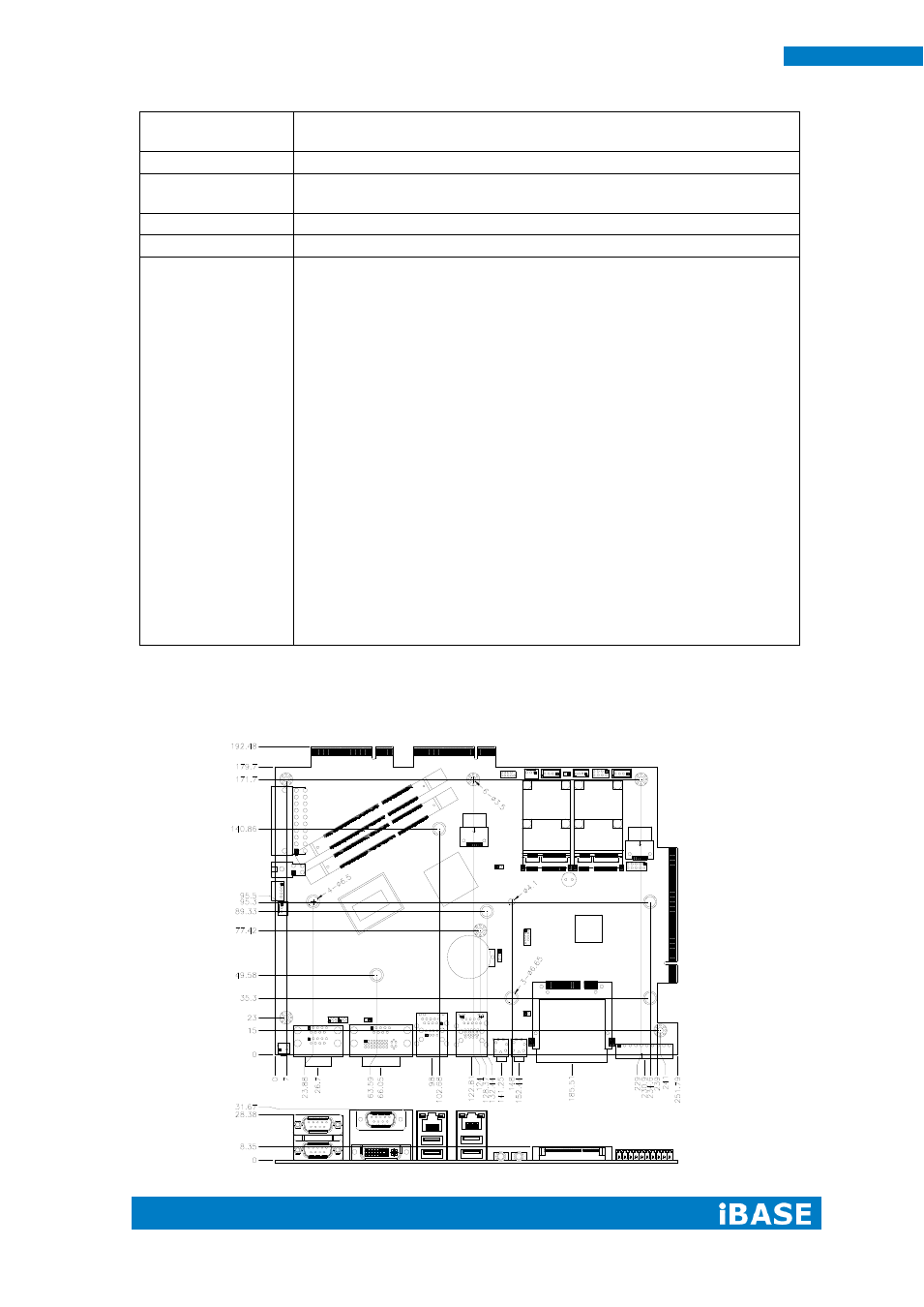
Board Dimensions