Assembly instruction, Pt4000 – ikan PT4000 User Manual
Page 3
3903 Stoney Brook Dr. Houston TX 77063 | +1.713.272.8822 | www.ikancorp.com | [email protected] | © 2009 ikan Corporation. All right reserved.
ASSEMBLY INSTRUCTION
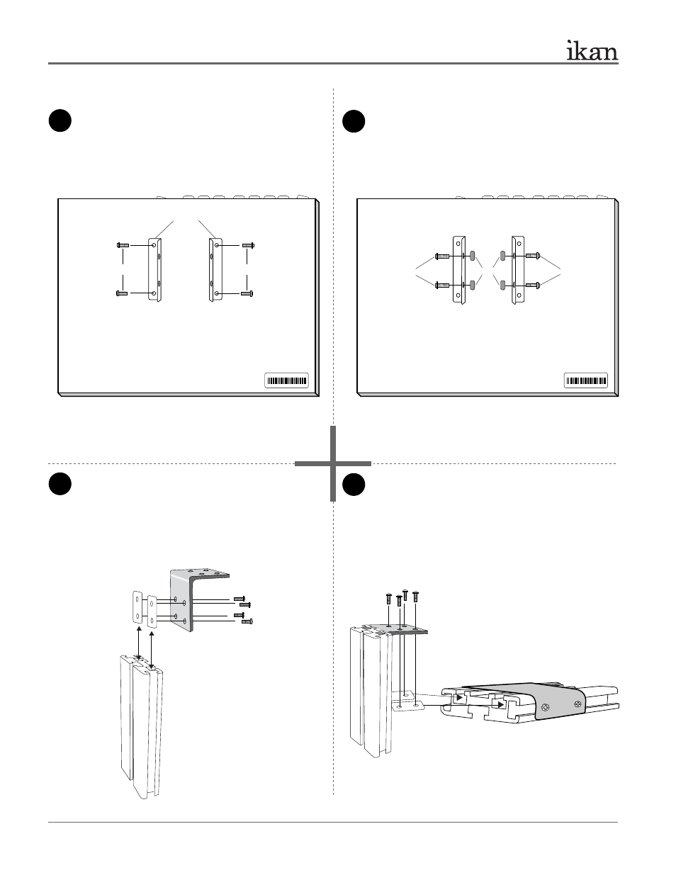
1
3
4
2
Attach the Mounting Bracket (Part J) to the back of the 20”
monitor using 4 x Short Phillip’s head screws (Part H).
The two flaps of Part Js should be perpendicular to the
monitor control buttons.
Attach the 20” T-slot with Metal Bracket (Part P) to the
assembled parts. You will use 2 x T-plates (Part C) and
4 x Long Phillips Head screws (Part G) to do so. Make
sure to evenly tighten all screws in this assembly.
Attach 4 x T-slot Nuts (Part D) and 4 x Long Phillips Head
Screws (Part G) as shown on the diagram.
PT4000
20” TELEPROMPTER
Part-I
Part-M
Part P
Attach L-Bracket (Part I) to 8” T-slot (Part M) using 2 x
T-plates (Part C) and 4 x Long Phillips head screws (Part
G). Refer to illustration below for configuration. The
L-Bracket’s (Part I) top half should be flush with the
edge of the 8” T-slot (Part M). Arrange the long section
of Part I attached to Part M.
Part-G
Part-G
Part-C
Part-C
PT4000
Rear view of 20” monitor
PT4000
Rear view of 20” monitor
Part-D
Part-G
Part-G
Part-H
Part-H
Part-J
+
+
+
+
Note: Do not completely tighten any screws until you have positioned
the monitor on the T-Slot.
Note: Make sure to tighten the
Long Phillips head screws down
as tight as possible. This will
support the weight of the monitor.
2 of 10