Insinger GalleyMaster Series User Manual
Page 14
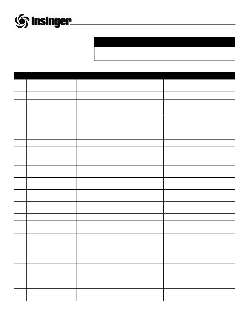
INTRODUCTION
The GalleyMaster Dishwasher is a heavy
duty machine designed for daily use in a
naval shipboard environment.
ITEM
CONTROL
TYPE
FUNCTION
1
Control power switch
Off-On selector switch on control panel
Controls 24 vac power to control cir-
cuit
2
Control power light
Yellow pilot light on control panel
Signals control power state
3
Start switch
Green pushbutton on control panel
Starts pumps and conveyor(s)
4
Stop switch
Red pushbutton on control panel
Stops pumps and conveyor(s)
5
Wash tank heat indicator
Yellow pilot light on control panel
Signals heating element energized in
wash tank
6
Rinse tank heat indicator
Yellow pilot light on control panel
Signals heating elements energized
in rinse tank
7
Check conveyor indicator
Red pilot light on control panel
Signals conveyor jam
8
5 amp circuit breaker
White circuit breaker on control panel
Over-current protection for control
circuit
9
Water ball valves
Valve located on respective piping string
Opens or closes incoming water line
10
Damper blade position
control
Handle (90° rotation) at vent duct connections Regulates vent duct exhaust flow
11
Wash tank water level
sight glass
Porthole located on front of wash tank
Indicates level of water in wash tank
12
Rinse tank water level
sight glass
Porthole located on front of rinse tank
Indicates level of water in rinse tank
13
Thermometers - wash
and rinse
Dial gauges located on front of wash and
rinse tanks
Indicate water temperature in wash
and rinse tanks
14
Thermometer - final rinse
Dial gauge located on top of final rinse piping
Indicates final rinse temperature
15
Pressure gauge - final
rinse
Dial gauge located on top of final rinse piping
Indicates final rinse pressure
16
Temperature control -
wash and rinse
Round slotted adjustment knob located on the
wash or rinse tank temperature control board
in the control panel
Regulates temperature of the wash
and rinse tank water
17
Low water level switch
Float switch located in wash and rinse tanks
Disables respective tank heating
element(s)
18
High water temperature
limit switch
Thermostat on wash and rinse heaters
Disables respective tank heating
element(s)
19
Final rinse temperature
control
Slotted adjustment screw located inside the
lower front of the booster
Controls temperature of final rinse
water
20
Final rinse high tempera-
ture limit switch
Manual reset thermostat located inside the
lower front of the booster
Disables booster heating elements
CONTROLS AND INDICATORS (ELECTRICALLY HEATED MACHINES)
CAUTION:
The operator should become thoroughly familiar with the equipment and
these operating instructions prior to starting the machine.
PART 1 TECHNICAL INFORMATION