JIMS Box 2 1208-1352 (all models of 120, 131, or 135 Alpha, Beta and Evo Mount Engines) User Manual
Page 14
555 Dawson Drive, Camarillo, CA 93012 Phone 805-482-6913 • Fax 805-482-7422
13
Rev I
8-12
No.1208-1352
A Division of Thiessen Products, INC
IIn
ns
st
tr
ru
uc
ct
tiio
on
n S
Sh
he
ee
et
t F
Fo
or
r B
Bo
ox
x 2
2 1
12
20
0”
”,, 1
13
31
1”
” o
or
r 1
13
35
5”
”
E
En
ng
giin
ne
e A
As
ss
se
em
mb
bl
liie
es
s O
Or
r E
En
ng
giin
ne
e R
Ra
ac
ce
e K
Kiit
ts
s
• Clamp the cylinder down so it will not move as you rotate the crank shaft.
See Fig. 52
• Slide a two inch length of stiff tubing or other spacer material over a short
head bolt.
Note: Use a short, 1/2” I.D. oil, or gas hose.
• Thread the bolt onto one of the cylinder studs until the spacer is finger-
tight against the cylinder. See Fig. 53.
• Installation: Front Cylinder See Fig. 54.
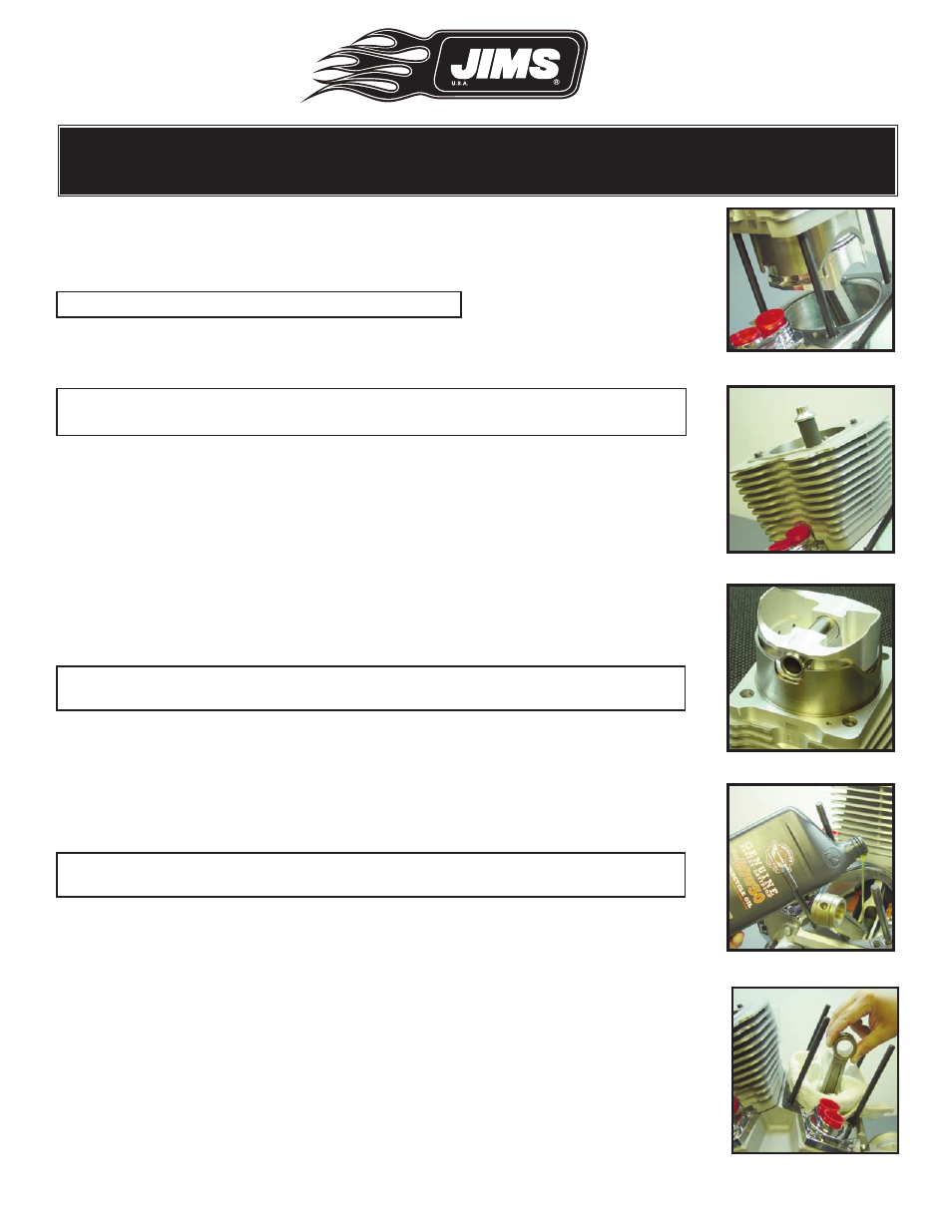
Note: Prior to front cylinder installation pour 1/3 of a quart of clean 20W-
50 H-D oil over the crankpin area. See Fig. 55.
• Rotate the crankshaft until the front connecting rod is at TDC. See Fig. 56
• Front cylinder installation is precisely similar to the rear’s.
• There are a couple of differences in the parts:
• The notch on the front cylinder spigot goes toward the rear of the
engine.
• The large valve relief in the top of the piston goes toward the rear of the
engine.
• The front piston has no skirt notch. See Fig. 34.
Installation: Cylinder Dowel Pins (No.1286-1387)
Note: Make sure the tappet block cover bores remain sealed so nothing can
fall into them.
• Lightly lube the larger beveled side of the dowel pin with clean H-D 20W-
50 oil.
• Install 2 dowel pins per cylinder into cylinder gasket surface area as
shown in Fig. 57.
Step 9: Cylinder Head Inspection and Assembly
Important Note: Any CNC ported heads used on JIMS 120, 131 or 135
Twin-Cam engines
All of JIMS heads found on 120, 131 or 135 engine’s are powder painted
either in black or silver prior to CNC porting. When the CNC porting
process is done some paint may remain inside the intake or exhaust ports.
Any paint that may be left inside ports will not affect airflow or performance
in any way. This is not a defect. do not try to remove it.
• Inspection See Fig. 58
• All sealing surfaces must be free of dents, deep scratches or foreign mate-
rial.
• Clean the cylinder gasket sealing surface with a lint-free cloth and dena-
tured/isopropyl alcohol and allow the surface to dry prior to installation.
This is particularly important with the JIMS 120, 131 or 135 Race Kit as its
special gaskets are hard and do not conform around deformities like the
softer stock gaskets.
Fig.52 - Verify gasket aligned
Fig.53 - Clamp cylinder
Fig.54 - Repeat for front
Fig.55 - Pour 1/3 quart oil
Fig.56 - Front rod TDC