Interrupteur marche/arrêt i/o, Fonctionnement du refroidisseur, Utilisation des panneaux de commandes – Kemppi Promig 520R User Manual
Page 13: Panneau de commandes mc, Hoofdschakelaar i/o, Werking van de vloeistofkoelunit, Werking van de functiepanelen, Mc -functiepaneel, Hauptschalter i / o, Bedienung des kühlgerätes (procool 10, procool 30)
PROMIG 520R, 120R / 0544 – 13
© KEMPPI OY
P21
R21
P22
R22
P23
S22
S21
S24
S25
S26
R23
S23
7. Open bottle valve slowly. Gas bottle pressure meter (F) shows bottle pressure.Note! Do not
use the whole contents of the bottle. Bottle should be filled when bottle pressure is 2 bar.
8. Open needle valve if there is one in the regulator.
9. Turn regulation screw (B) until hose pressure meter (G) shows the required flow (or pressure).
When regulating flow amount, power source should be switched on and gun switch pressed
simultaniously.
Close bottle valve after having finished welding. If the machine will be out of use for a long time,
unscrew pressure regulation screw.
3.8. MAIN SWITCH I/O
When you turn the main switch of PRO power source into position I, pilot lamp next to it is lit and
the equipment is ready for welding. The equipment reverts to the welding method used before the
main switch was turned to position zero.
Always start and switch off the machine with the main switch, never use the mains
plug as a switch.
3.9. OPERATION OF COOLING UNIT
(PROCOOL 10, procool 30)
Operation of cooling unit is controlled so that pump is turned on when welding is started. After
welding stop pump is rotating for approx. 5 min, thus cooling the liquid to ambient temperature.
Read in operation instructions for cooling unit the trouble situations in liquid circulation system
and protection against damage of gun etc.
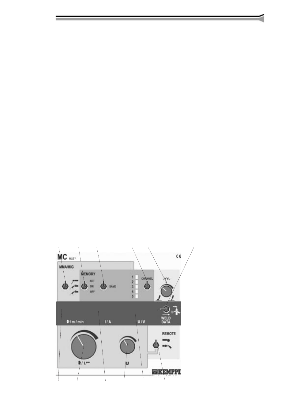
4. CONTROL PANEL OPERATIONS
4.1. MC CONTROL PANEL