Installation – Kleenmaid OMFFS9010 User Manual
Page 4
PROVISION FOR VENTILATION
INSTALLATION
The room where the Cooker is installed should have permanent
ventilation as follows:
Ventilation must be in accordance with AS5601/AG 601 - Gas
Installations. In general, the appliance should have adequate
ventilation for complete combustion of gas, proper flueing and to
maintain temperature of immediate surroundings within safe limits.
- Do not install in a bed-sitting room, a bathroom or shower room.
If there is another fuel burning appliance in the same room, a
higher level of ventilation will be required, you should consults
" the safety requirements".
In addition to the above, during prolonged use, opening a window
in the same room is recommended. This will avoid the build up
of excessive moisture and condensation.
4
Fig. 1
Fig. 1A
BACK SIDE
V
V
F
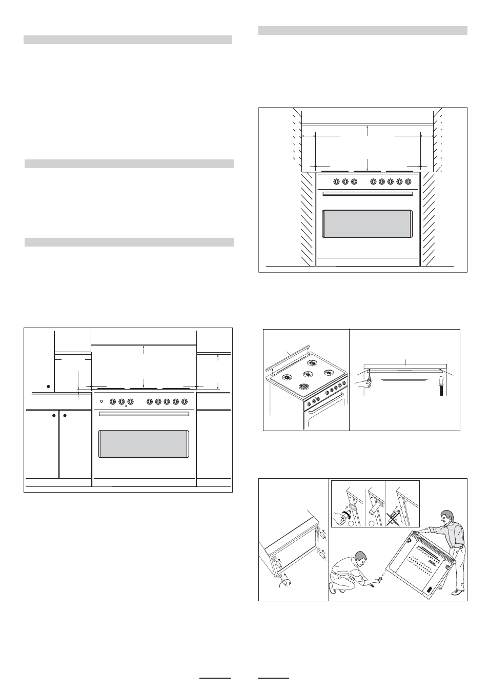
POSITIONING
Important: Fix the chain located next to the gas connection on
both sides of the cooker to the wall to prevent the cooker from
tilting. Both chains must be securely fixed.
Make sure that the wall surface behind the Cooker is non-
combustable (will not catch fire).
Where a painted surface is adjacent, a fire retardent paint surface
is recommended. Wallpaper, wood, or fabric should not be used
behind or next to the cooker.
Any adjoining wall surface (side or rear) situated within 200mm
of any hob burner must be a suitable non-combustible material
from the edge for a height of 150mm for the entire length
of the cooker.
Any combustible construction above the cooker must be at least
650mm above the maintop. Ensure that a power and gas supply
are nearby. The Cooker should be located carefully so that the
heat produced by it has plenty of space to escape. The diagram
below shows an ideal configuration.
If the cooker is being fitted next to cupboards or adjoing wall
surfaces, which are within 200mm from the edge of the hob
burner and of a suitable non-combustible material as specified
min.100 mm
min.
650 mm
min.
400 mm
"0" mm
"0" mm
Clearances to combustible materials
No part of any adjoining wall surface can be made of combustible
materials. The protection of combustible materials
required by Clause 5.12.1.1 of AS5601-2004 is the fixing of 5 mm
thick ceramic tiles to the surface or attaching fire resistant
material to the surface and covering with sheet metal with a minimum
thickness of 0.4 mm.
Clearances to non- combustible materials
min.
650 mm
"0" mm
"0" mm
min "60" mm
min "60" mm
min "60" mm
non-
combustible materials
non-
combustible materials
in AS5601, then ensure that a distance of at least 6cm is left
between the edge of the cooker and the non-combustible
material. This gap is to allow plenty of space for the heat
produced by the cooker to escape on each side of the cooker.
min.10
mm
Note:
the cooker is fitted with a metallic rear hob protecting
profile (F, see fig. 1) which must be assembled in
following way:
- put the profile (F) on the rear part of the cooker as in fig.
1, and screw the delivered screws (V) as in fig. 1A.
Note:
The cooker is fitted with 4 legs for an eventual alignment in height
with the furniture ( fig. 1 B ).
WARNING: This appliance is not suitable to be installed on
a base
Fig. 1 B
F
OK
NO
1
2