La Crosse Technology WS-9060U-IT User Manual
Page 3
9
Indoor
relative
humidity
in RH%
Indoor
temperature
in ºC/ºF
If the weather station is moved to another location
significantly higher or lower than its initial standing point
(for example from the ground floor to the upper floors of a
house), discard the weather forecast for the next 12-24
hours. By doing this, the Weather Station will not mistake
the new location as being a possible change in air-
pressure when really it is due to the slight change of
altitude.
WEATHER TENDENCY INDICATOR
Working together with the weather icons is the weather
tendency indicators (located on the left and right sides of
the weather icons). When the indicator points upwards, it
means that the air-pressure is increasing and the weather
is expected to improve, but when indicator points
downwards, the air-pressure is dropping and the weather
is expected to become worse.
Taking this into account, one can see how the weather has
changed and is expected to change. For example, if the
indicator is pointing downwards together with cloud and
sun icons, then the last noticeable change in the weather
was when it was sunny (the sun icon only). Therefore, the
next change in the weather will be cloud with rain icons
since the indicator is pointing downwards.
Note:
Once the weather tendency indicator has registered a
change in air pressure, it will remain permanently
visualized on the LCD.
INDOOR TEMPERATURE/HUMIDITY DATA
The indoor temperature and humidity data are
automatically updated and displayed on the fourth section
of the LCD.
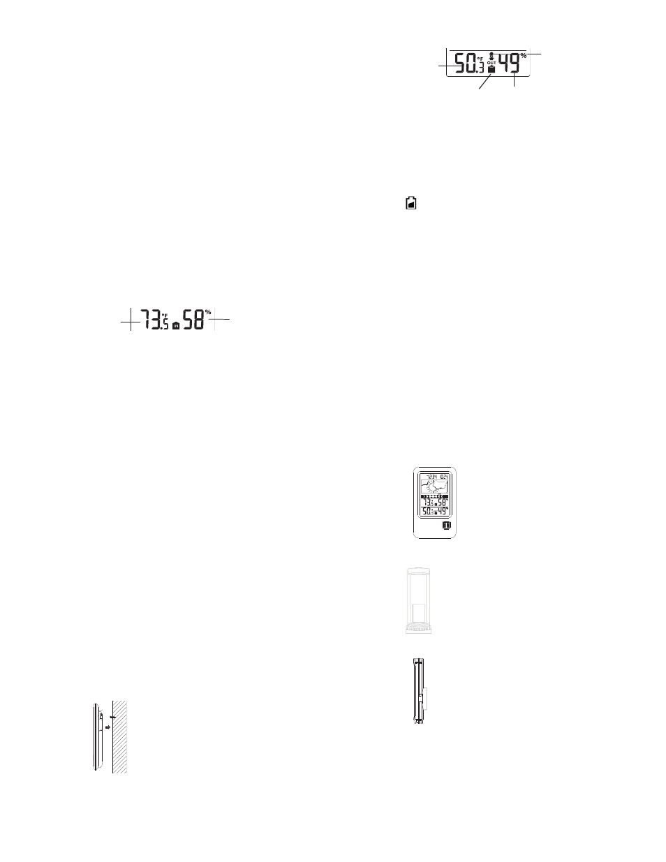
OUTDOOR TEMPERATURE/HUMIDITY DATA
The last LCD section shows the outdoor temperature and
humidity, and the reception indicator.
10
Outdoor data signal
reception indicator
Outdoor
temperature
in ºC/ºF
Outdoor relative
humidity in RH%
TOGGLING AND RESETTING THE MIN/MAX DATA
VIEW THE MIN/MAX DATA
Press the MIN/MAX key several times to view the
MIN/MAX indoor temperature, and MIN/MAX outdoor
temperature sequentially.
RESET THE MIN/MAX DATA
Press and hold MIN/MAX key for 3 seconds to reset all
the indoor and outdoor temperature to current
temperatures.
LOW BATTERY INDICATOR
Low battery indicator is displayed on the LCD by the time
when the batteries require changing in the display. The
low battery indicator is displayed in the outdoor
temperature area when the batteries in the transmitter
require changing.
ABOUT THE THERMO-HYGRO TRANSMITTER
The temperature may affect the range of the thermo-hygro
transmitter. At cold temperatures the transmitting distance
may be decreased. Please bear this in mind when
positioning the transmitters. Also the batteries may be
reduced in power for the thermo-hygro transmitter.
CHECKING FOR 915MHz RECEPTION
If the outdoor temperature and humidity data are not being
received within two minutes after set up (or outdoor
display always show “- -.-” in the outdoor section of the
Weather station during normal operation), please check
the following points:
1.
The distance of the weather station or transmitters
should be at least 5 to 6.5 feet (1.5 -2 meters) away
from any interfering sources such as computer
monitors or TV sets.
Low battery
indicator
(transmitter)
11
2.
Avoid placing the transmitters onto or in the
immediate proximity of metal window frames.
3.
Using other electrical products such as headphones
or speakers operating on the 915MHz-signal
frequency may prevent correct signal transmission
or reception.
4.
Neighbors using electrical devices operating on the
915MHz-signal frequency can also cause
interference.
Note:
When the 915MHz signal is received correctly, do not re-
open the battery cover of either the transmitter or weather
station, as the batteries may spring free from the contacts
and force a false reset. Should this happen reset all units
(see “Set up” above) otherwise transmission problems
may occur.
The transmission range is around 330 feet (100 meters)
from the thermo-hygro transmitter to the weather station
(in open space). However, this depends on the
surrounding environment and interference levels. If no
reception is possible despite the observation of these
factors, all system units have to be reset (see “Set up”
above).
POSITIONING THE WEATHER STATION
The weather station provides the option of table standing
or wall mounting the unit. Before wall mounting, please
check that the outdoor data can be received from the
desired locations.
To wall mount:
1.
Fix a screw (not supplied) into the
desired wall, leaving the head
extended out by about 5mm.
2.
Place the weather station onto
the screw, using the hanging hole
on the backside. Gently pull the
weather station down to lock the
screw into place.
12
Foldout table stand:
The foldout table stand is located on
the backside. Pull the stand out from
the bottom center edge of the weather
station, below the battery
compartment. Once the foldout table
stand is extended, place the weather
station in an appropriate location.
POSITIONING THE THERMO-HYGRO
TRANSMITTER
To wall mount:
1.
Secure the bracket onto a desired wall
using the screws and plastic anchors.
2.
Clip the transmitter onto the bracket.
Note:
Before permanently fixing the thermo-hygro to
the wall base, pace all units in the desired
locations to check that the outdoor temperature
and humidity readings are receivable. In event
that the signal is not received, relocate the thermo-hygro
transmitter or the weather station slightly as this may help
the signal reception.
CARE AND MAINTENANCE:
x
Extreme temperatures, vibration and shock should
be avoided as these may cause damage to the units
and give inaccurate forecasts and readings.
x
When cleaning the display and casings, use a soft
damp cloth only. Do not use solvents or scouring
agents as they may mark the LCD and casings.
Mount in a sheltered place. Avoid
direct rain and sunshine.
The thermo-hygro transmitter can be
placed onto any flat surface or wall
mount using the bracket which
doubles as a stand or wall mount
base.