Mrhc3, Mrrc3 – Legrand MRHC3 User Manual
Page 2
In
st
a
ll
a
ti
o
n
In
st
ru
ct
io
n
s
SPECIFICATIONS
UL and cUL Listed
Input Voltage .............................12-24VDC, 200mA minimum
Control Inputs ...............3-24VDC, 33ms hold time minimum
Output ............................................24VDC, 150mA maximum
AC-DC adaptor (provided)
Input ...............................................................120VAC, 60Hz
Output .......................................................... 24VDC, 200mA
DESCRIPTION
The MRHC3 and MRRC3 Scene Interfaces offer Top Dog™
wireless network interconnectivity to common electronic
control devices. With this interconnectivity, house and
room scenes are invoked based on inputs from the
external control device. Application examples include
alarm systems, astronomic time clocks, motion sensors
and garage doors integrated with the wireless network to
execute house and room scenes.
TOP DOG™ WIRELESS COMMuNICATION
Wireless devices use radio signals to communicate with
each other to control lighting and other types of electric
loads in selected areas. These wireless devices use the
900MHz band for high-speed control communication. Using
the “frequency-agile” Top Dog™ technology, these wireless
devices avoid interference with other 900MHz devices, such
as cordless phones and baby monitors.
OPERATION
The scene interfaces can be setup in one of two operating
modes to accept either maintained or momentary inputs.
They can initiate scenes based on active high, active low,
maintained or momentary control signals. For momentary
applications, a minimum hold time of 33ms is required so
the scene interface can process the change-of-state. The
scene assignments are fixed and cannot be changed.
Mode A, typically used with momentary control signals,
uses scenes 6 and 8 for inputs 1 and 2. Input 3 invokes the
house or room on/off scene of a controller paddle.
Mode B, typically used with maintained control signals,
uses scenes 6, 7, 8 and 9 for inputs 1 and 2. Input 3 on the
MRHC3 invokes the house “panic” scene, and on the MRRC3
it can be used to inhibit execution of scenes bound to the
other inputs.
The MRHC3 interface is a house level scene controller.
Please refer to Table 1 and Table 2 for more information
about its operating modes.
The MRRC3 interface is a room level scene controller.
Please refer to Table 3 and Table 4 for more information
about its operating modes.
POWER FAIL MEMORY
After a power failure, all wireless devices automatically
return to the state that they were in immediately prior to loss
of power. All configuration and scene control information is
preserved.
APPLICATION ASSISTANCE
The Scene Interfaces function as part of a network that
may contain a variety of wireless devices. Instructions
for installation, binding operations, and use are included
with the relevant wireless devices. Application support
information and installation guides for Legrand wireless
network devices are available online.
INSTALLATION
The interface can be installed in an equipment room, garage
or user occupied space within radio range of the wireless
network devices and within convenient wiring distance to the
external output device.
A screw slot on the base of the unit is provided for wall
mounting. Radio communication cannot be guaranteed if the
unit is mounted in a metallic electrical enclosure.
1. Complete the physical installation and binding of
all other wireless devices in the network. Use an
appropriate scene controller or hand held scene remote
programmed for scene set 6-10 to set up the scenes
that will be executed based on the inputs from the
MRHC3 or MRRC3. See “More Scenes” in the installation
instructions provided with the controller or remote to
program the device for scenes 6-10.
2. Wire the external devices to the appropriate terminals on
the MRHC3 or MRRC3, according to the instructions in
the WIRING APPLICATIONS section of this manual.
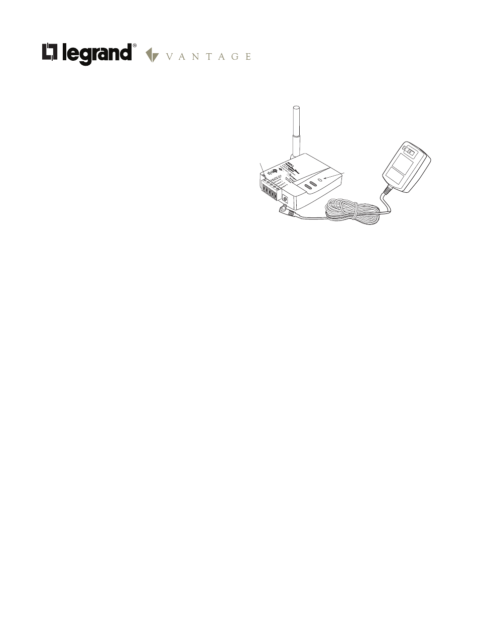
3. Plug the power supply into a convenient 120VAC outlet,
and connect the power cord to the MRHC3 or MRRC3’s
power socket.
4. The status LED lights yellow, indicating that the unit
is ready for configuration. See SET HOUSE ID in this
manual.
MRHC3
and
MRRC3
House and Room Scene Inerfaces
House or Room
Scene Interface
Power Supply
Status LED
Removable
Terminal
Block