Wiring applications, User interface, Pushbuttons – Legrand MRHC3 User Manual
Page 3
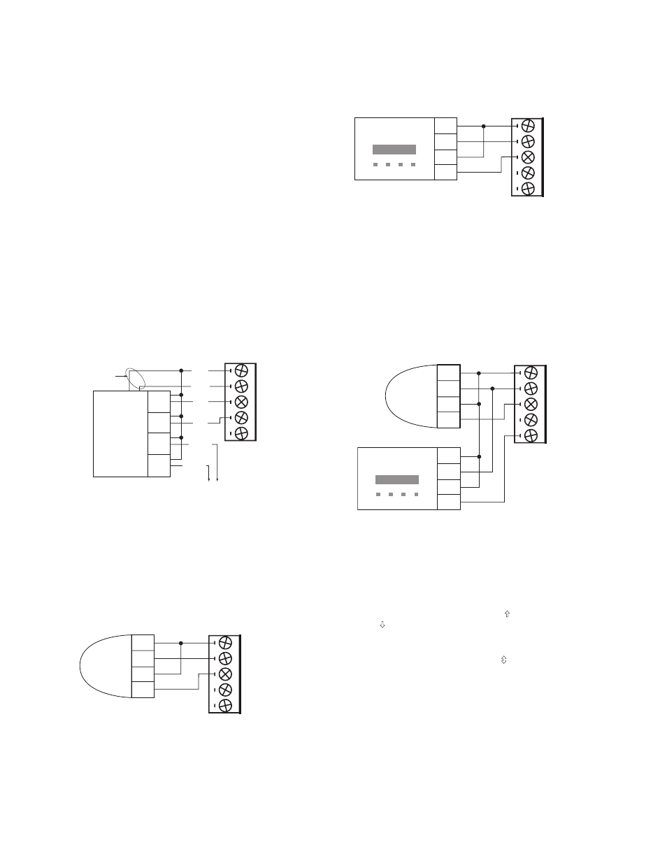
WIRING APPLICATIONS
All wiring to the MRHC3 and MRRC3 is Class 2 low voltage
and shall meet local code for Class 2 Equipment wiring.
Both interfaces use removable screw terminal blocks
for easy wiring access. Power to the scene interfaces is
provided by a plug-in power supply.
Output Power: Two terminals allow the interfaces to power
external sensors: 24VDC and Ground. The 24VDC output
is capable of supplying up to 150mA to power external
occupancy sensors or other devices.
Primary applications include motion sensors, alarm
systems, time clock and home/away functions when
interfaced to a garage door. The followng sections provide
wiring instructions specific to each type of application along
with operating mode suggestions.
Garage Door
Interface the MRHC3 or MRRC3 to a multi-channel garage
door controller with at least 3 channels. Use two channels to
execute the home and away features, while the third channel
toggles the garage door open or closed. On a 4-channel
interface, the 4th channel can operate a gate or second door.
Use Mode-A to set up the MRHC3 or MRRC3 for home and
away applications.
Motion Sensor
A motion sensor application could use either Mode-A or
Mode-B. Most applications would use Mode-B. In this
configuration, a scene executes when the sensor initially
detects motion and a second scene executes when the
motion sensor determines that the space is unoccupied.
However, Mode-A allows Auto-ON, Manual-OFF and Manual-
ON Auto-OFF functions. A manual-ON Auto-OFF application
requires the input to be wired to a NC contact and the scene
stored to turn the appropriate lighting off.
Astronomic Time Clock
A time clock application is nearly identical to that of a motion
sensor. Mode-B allows a transition between two scenes, or
Mode-A executes a single scene.
MRRC3 (Only) — Scene Inhibit
The purpose of the scene inhibit feature in Mode-B is to lock
out signals on input 1 and 2 when input 3 is high. When input
3 goes high, signals to inputs 1 & 2 are ignored. This function
is commonly used with a motion detector in conjunction with
a time clock or similar device.
When input 3 goes low, signals at input 1 and input 2 will
recall scenes as appropriate for MRRC3 Mode-B binding
(see Table 4).
uSER INTERFACE
The user interface consists of two pushbuttons and a multi-
color LED for device status.
PuSHBuTTONS
The pushbuttons are the Top button ( ) and the Bottom
button ( ).
Binding Operations
Press both buttons simultaneously ( ) for about 2 seconds to
initiate binding operations.
Operating Mode Selection
See Switching Operating Modes, next page.
Reset to Factory Default/unconfigure
When both the buttons are simultaneously pressed for a
period of 10 seconds, the device performs a system reset
and clears all memory contents. This resets the device to
an unbound un-configured state (the LED changes to solid
yellow).
Room or House
Scene Interface
Input 1
Input 2
Input 3
24VDC Out.
150ma max.
Ground
4-Channel
Garage
Door
Control
1
3
4
2
COM
NO
NC
COM
NO
NC
COM
NO
NC
COM
NO
NC
DOOR(2)
DOOR(1)
Ground
Home
Away
Power
Optional
Room or House
Scene Interface
Input 1
Input 2
Input 3
24VDC Out.
150ma max.
Ground
Motion
Sensor
Ground
COM
NO
Power
Input 1
Input 2
Input 3
24VDC Out.
150ma max.
Ground
Time Clock
Ground
COM
NO
Power
Room or House
Scene Interface
MRRC3 Room
Scene Interface
(Only)
Input 1
Input 2
Input 3
24VDC Out.
150ma max.
Ground
Motion
Sensor
Ground
COM
NO
Power
Time Clock
Ground
COM
NC
Power