Dmx512 explained – LSC Lighting MDR Splitter User Manual
Page 7
MDR DMX512/RDM Data Splitter Operator Manual
LSC Lighting Systems (Aust) Pty Ltd.
Page 5
DMX512 Explained
DMX512-A is the industry standard for the transmission of digital control signals between
lighting equipment. It utilises just a single pair of wires on which is transmitted the level
information for the control of up to 512 DMX slots (addresses or channels).
The information for each slot is sent sequentially. The level of slot 1 is transmitted, then the
level of slot 2, then 3, etc. up to a maximum of 512 slots. This stream of data containing
the levels for all 512 DMX slots is repeated a minimum (generally) of 44 times per second.
This provides sufficient updates of channel information for smooth fade transitions.
As the DMX512-A signal contains the level information for all slots, each piece of equipment
needs to be able to read the level(s) of the slots(s) that apply only to that piece of
equipment.
DMX512 Cables
When good quality data cables are used, DMX512 cable runs may be up to 1,000 metres in
length. When several DMX streams are required (to feed different locations), DMX512
splitters must be used. These provide multiple isolated DMX512 output streams of the same
input stream.
Note: Do not use unscreened microphone or low speed data cables for DMX. This can cause
problems in the DMX network. Make sure the cable conforms to the EIA485 cable
requirements by providing the following specifications:
Low capacitance
One or more twisted pairs
Foil and braid shielded
Impedance of 85 -150 Ohms, nominally 120 Ohms
22AWG gauge for continuous lengths over 300 metres
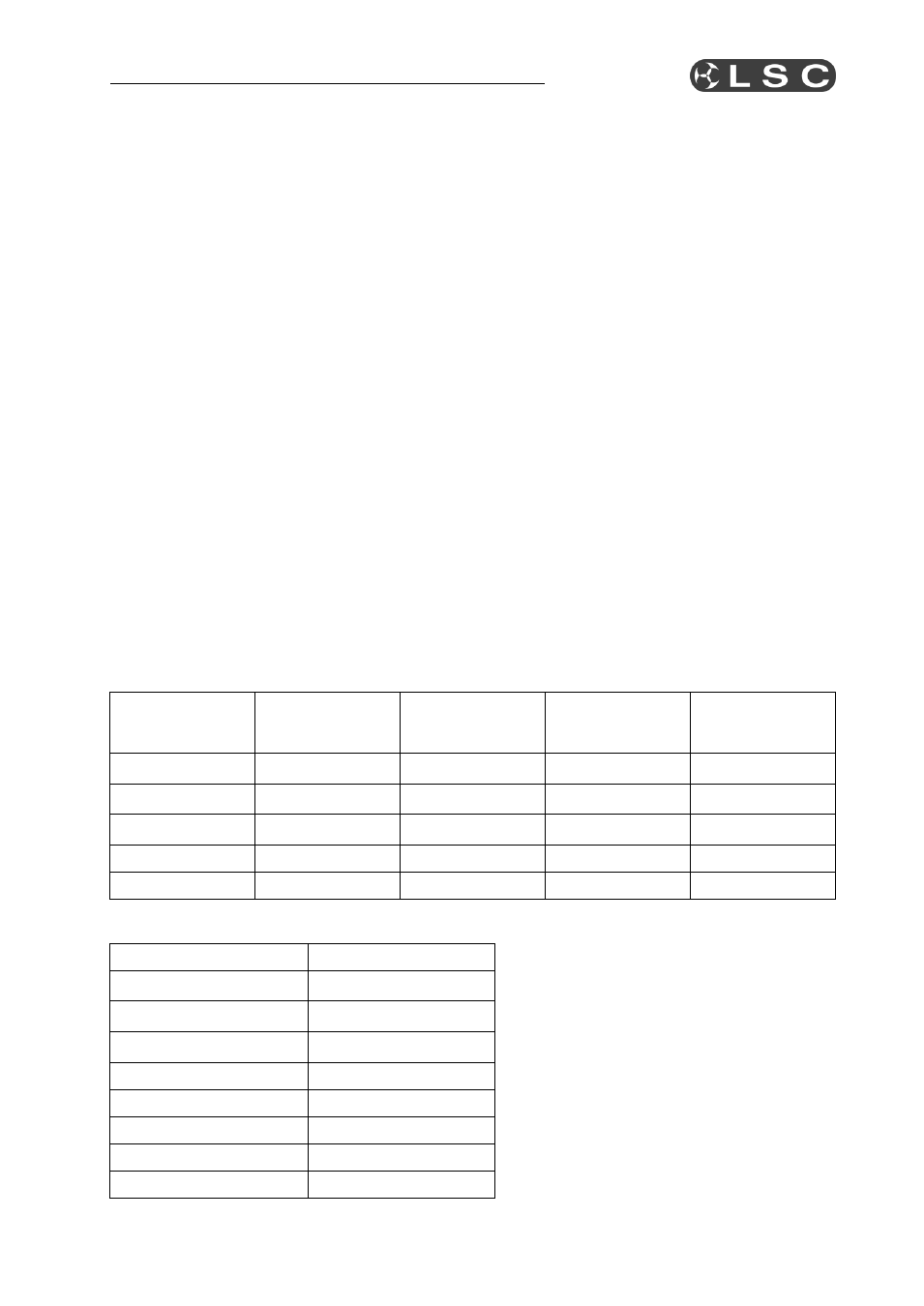
DMX512 Connector pin assignments
Connector pin
number
XLR 5-pin input
connector
XLR 5-pin thru
connector
XLR 5-pin
output
connectors
XLR 3-pin
output
connectors
Pin 1
Common
Common
Ground
Ground
Pin 2
DMX –ve in
DMX –ve thru
DMX –ve out
DMX –ve out
Pin 3
DMX +ve in
DMX +ve thru
DMX +ve out
DMX +ve out
Pin 4
Looped through
Looped through
Looped through
Not used
Pin 5
Looped through
Looped through
Looped through
Not used
RJ45 DMX Connector pin assignments
Connector pin number
RJ45 8-pin connector
Pin 1
DMX +ve
Pin 2
DMX –ve
Pin 3
Not Connected
Pin 4
Not Connected
Pin 5
Not Connected
Pin 6
Not Connected
Pin 7
Common
Pin 8
Common