Maytag WMH76719CB Dimension Guide User Manual
Page 2
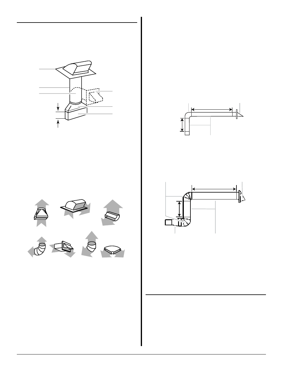
VENTING REQUIREMENTS
Because Whirlpool Corporation policy includes a continuous commitment to
improve our products, we reserve the right to change materials and specifications
without notice.
Dimensions are for planning purposes only. For complete details, see
Installation Instructions packed with product. Specifications subject to
change without notice.
Page 2 of 2
Rectangular to Round Transition:
Recommended Standard Fittings
The following length equivalents are for use when figuring vent
length. See the examples in “Recommended Vent Length.”
NOTE: The minimum 3" (7.6 cm) clearance must exist
between the top of the microwave oven and the
rectangular to round transition piece so that the damper
can open freely and fully.
27" (68.6 cm) models
A. Roof cap
B. 6" (15.2 cm) min. diameter round vent
C. Elbow (for wall venting only)
D. Wall cap
E. 31⁄4" x 10" to 6" (8.3 x 25.4 cm to 15.2 cm)
rectangular to round transition piece
F. Vent extension piece, at least 3" (7.6 cm) high
A. Rectangular to round transition piece: 31⁄4" x 10" to 6" = 5 ft
(8.3 x 25.4 cm to 15.2 cm = 1.5 m)
B. Roof cap: 31⁄4" x 10" = 24 ft (8.3 x 25.4 cm = 7.3 m)
C. 90° elbow: 3 " x 10" = 25 ft (8.3 x 25.4 cm = 7.6 m)
D. 90° elbow: 6" = 10 ft (15.2 cm = 3 m)
E. Wall cap: 31⁄4" x 10" = 40 ft (8.3 x 25.4 cm = 12.2 m)
F. 45° elbow: 6" = 5 ft (15.2 cm = 1.5 m)
G. 90° flat elbow: 31⁄4" x 10" = 10 ft (8.3 x 25.4 cm = 3 m)
Recommended Vent Length
A 3
1
⁄
4
" x 10" (8.3 x 25.4 cm) rectangular or 6" (15.2 cm) round
vent should be used.
The total length of the vent system including straight vent,
elbow(s), transitions and wall or roof caps must not exceed
the equivalent of 140 ft (42.7 m) for either type of vent. See
“Recommended Standard Fittings” section for equivalent
lengths.
For best performance, use no more than three 90° elbows.
To calculate the length of the system you need, add the
equivalent lengths of each vent piece used in the system.
See the following examples:
3
1
⁄
4
" x 10" (8.3 x 25.4 cm) vent system = 73 ft
(22.2 m) total
A. One 3
1/4
" x 10" (8.3 x 25.4 cm) 90° elbow = 25 ft (7.6 m)
B. 1 wall cap = 40 ft (12.2 m)
C. 2 ft (0.6 m) + 6 ft (1.8 m) straight = 8 ft (2.4 m)
6" (15.2 cm) vent system = 73 ft (22.2 m) total
A. Two 90° elbows = 20 ft (6.1 m)
B. 1 wall cap = 40 ft (12.2 m)
C. 1 rectangular to round transition piece = 5 ft (1.5 m)
D. 2 ft (0.6 m) + 6 ft (1.8 m) straight = 8 ft (2.4 m)
If the existing vent is round, a rectangular to round transition
piece must be used. In addition, a rectangular 3" (7.6 cm)
extension vent between the damper assembly and rectangular
to round transition piece must be installed to keep the damper
from sticking.
LOCATION REQUIREMENTS
Special Requirements
For Wall Venting Installation Only:
•
Cutout must be free of any obstructions so that the vent
fits properly, and the damper blade opens freely and fully.
For Roof Venting Installation Only:
•
If you are using a rectangular to round transition piece, 3"
(7.6 cm) clearance needs to exist above the microwave
oven so that the damper blade can open freely and fully.
See “Rectangular to Round Transition” illustration in
“Venting Design Specifications” section.
A
B
C
E
F
D
3" (7.6 cm)
A B
C
6 ft (1.8 m)
2 ft
(0.6 m)
A B
C D
6 ft (1.8 m)
2 ft
(0.6 m)
A B C
D E F G
Ref. W10724870A
05/15