Maytag MMC5000BDB Installation User Manual
With use on model mmc 5000 microwave oven, Warning
INSTALLATION
INSTRUCTIONS
Microwave Oven Built-In Kit
Model MMA27 And MMA30
With Use On Model MMC 5000 Microwave Oven.
OBSERVE ALL GOVERNING CODES AND ORDINANCES.
STEP 1: Electrical Requirements
A. A 120-Volt, 60 Hz, AC, 15 ampere, fused electrical supply is required
(time-delay fuse or circuit breaker is recommended). However, if your
home has a circuit wired and fused for 20 amperes, this is preferred. If
you are installing a new circuit, one wired and fused for 20 amperes is
recommended. It is also recommended that a separate circuit serving
only this appliance be provided. Do not use an extension cord.
B. ELECTRICAL CONNECTION: ELECTRICAL GROUND IS RE-
QUIRED ON THIS APPLIANCE. DO NOT UNDER ANY CIR-
CUMSTANCES, REMOVE THE POWER SUPPLY CORD GROUND
PRONG.
FIGURE 1
Required Grounding Method
3-Prong Grounding Plug
Power Supply Cord
Properly Polarized 3-Hole
Grounding Type Wall Receptacle
For your personal safety, this appliance must be properly grounded and
polarized. This appliance is equipped with a power supply cord having
a 3-prong grounding plug. To minimize possible shock hazard, the cord
must be plugged into a mating 3-hole grounding type wall receptacle,
grounded in accordance with the National Electrical Code, local codes
and ordinances. If a mating wall receptacle is not available, it is the
personal responsibility and obligation of the customer to have a
properly grounded and polarized 3-hole wall receptacle installed by a
qualified electrician. (See figure 1).
NOTE: A 27² minimum wide cabinet must be provided to install Trim Kit
MMA27.
NOTE: A 30² minimum wide cabinet must be provided to install Trim Kit
MMA30.
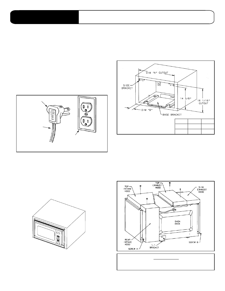
STEP 2: Cabinet Opening
The opening should be per dimensions described below. All corners should
be square. The floor of the opening must be plywood and must be level and
capable of supporting 80 lbs.
FIGURE 2
MODEL
MMA27
MMA30
DIM. “A”
25-1/2²
28-3/16²
DIM. “B”
2-3/4²
4-1/16²
STEP 3: Assembly Of Intake Hood
(See Figure 3)
A. Remove screw A.
B. Place rear intake hood against rear of microwave.
C. Align hole in rear intake hood and microwave unit, reinstall screw
removed in step A.
Note: Route microwave cord through cable relief hole.
D. Place top intake hood so hole at front aligns with hole in microwave unit
front.
E. Install 2² shoulder screw to attach top intake to microwave unit.
F. Install rear screw to attach top intake hood to rear intake.
FIGURE 3
WARNING
The weight of the microwave may exceed your lifting
ability. We recommend assistance.
8101P346-60
(11-99-00)