Important, Caution, Save for local electrical inspector’s use – Maytag MMC5000BDB Installation User Manual
Page 2
STEP 4: Assembly Of Exhaust Hood
(See Figure 3)
A. Remove screw B.
B. Place side exhaust hood against the rear and side of microwave unit.
C. Align hole in side exhaust and mirowave unit, reinstall screw removed
in step A.
D. Install side exhaust front screw to attach side exhaust hood to the
microwave unit.
E. Place top exhaust hood so hole at front aligns with hole in microwave
unit.
F. Install 2² shoulder screw to attach top exhaust hood to microwave unit.
G. Install rear screw to attach top exhaust hood to side exhaust hood side.
STEP 5: Installation Of Microwave “L” Bracket
(See Figure 3)
A. Attach “L” bracket with #10 screw to lower rear panel of microwave.
STEP 6: Installation Of Microwave Mount Bracketry
(See Figure 2)
Side Brackets
A. Measure 14 5/8² up from the bottom of the cutout to the bottom edge
of the side mounting brackets.
B. Use two flat head screws to attach each side mounting bracket to the
cabinet side walls as shown.
NOTE: Side mounting bracket should be pushed flush to cabinet face.
Microwave Base Bracket
A. With dimension “B” from figure 2, measure and mark location for
microwave base bracket.
B. With the two truss head screws, attach microwave base bracket to the
floor of cabinet as shown.
STEP 7: Installation Of Microwave
A. Plug power cord of oven into receptacle.
B. Slide the microwave feet into locating slots in microwave base bracket.
NOTE: Microwave rear cabinet should be flush to microwave base
bracket rear flange.
C. Slide “L” bracket over the two shoulder screws on bottom side of
microwave.
D. With two flat head screws, attach “L” bracket and microwave base
bracket to cabinet face. (See figure 4)
E. Attach trim assembly as shown in figure 4. Insert bottom of trim
assembly into lower support and rotate upward. Mark location of screw.
Remove trim and drill 9/64 pilot hole at marked locations and reinstall
trim, attach top of trim to cabinet with 2 flat head screws.
FIGURE 4
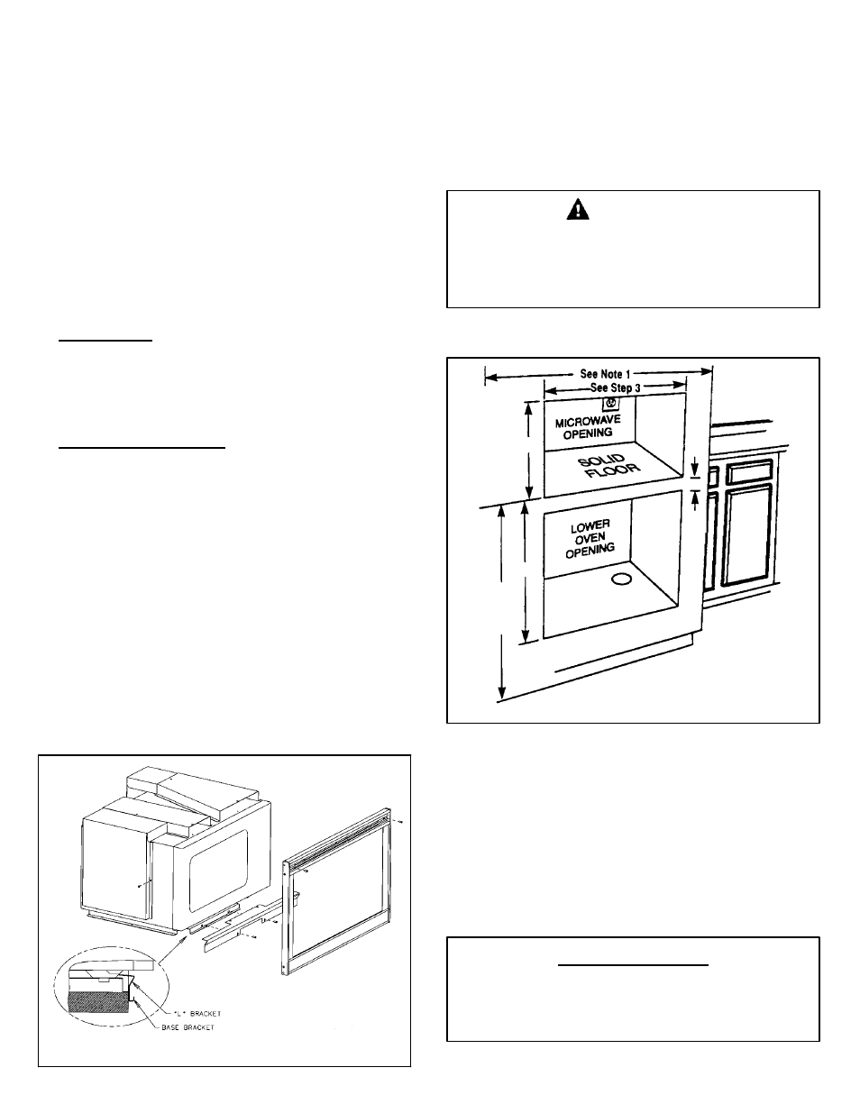
INSTALLATION ABOVE LOWER OVEN
NOTE: When installing this kit above a built-in oven, check built-in oven
installation instructions to determine cutout dimensions for the (lower) wall
oven.
NOTE: For a new installation, the 48² height dimension to the bottom of the
cutout for the microwave oven is recommended. This places the microwave
oven bottom at approximately 50² from the floor. See figure 5.
When the microwave oven is installed above a wall oven,
the minimum height dimension from the bottom of the wall
oven cutout to the bottom of the microwave cutout must be
maintained.
CAUTION
MIN.
1²
28-3/4²
16-1/16²
48²
(See
Note
2)
FIGURE 5
MMA27 Kits
may be used with microwave model MMC5000 installed
above 27² wall oven models bearing manufacturer No. E25378, when
installed in accordance with Manufacturer’s Installation Instructions. These
include models MEW5527 & MEW6527.
MMA30
may be used with microwave model MMC5000 installed above30²
wall oven models bearing manufacturer No. E25378, when installed in
accordance with Manufacturer’s Installation Instructions. These include
models MEW5530 & MEW6530.
Manufacturer’s No. can be obtained from the serial plate on the wall oven.
IMPORTANT
SAVE FOR LOCAL ELECTRICAL
INSPECTOR’S USE