4 8-bit digital i/o registers – Measurement Computing CIO-DAS6402/12 User Manual
Page 21
5.4
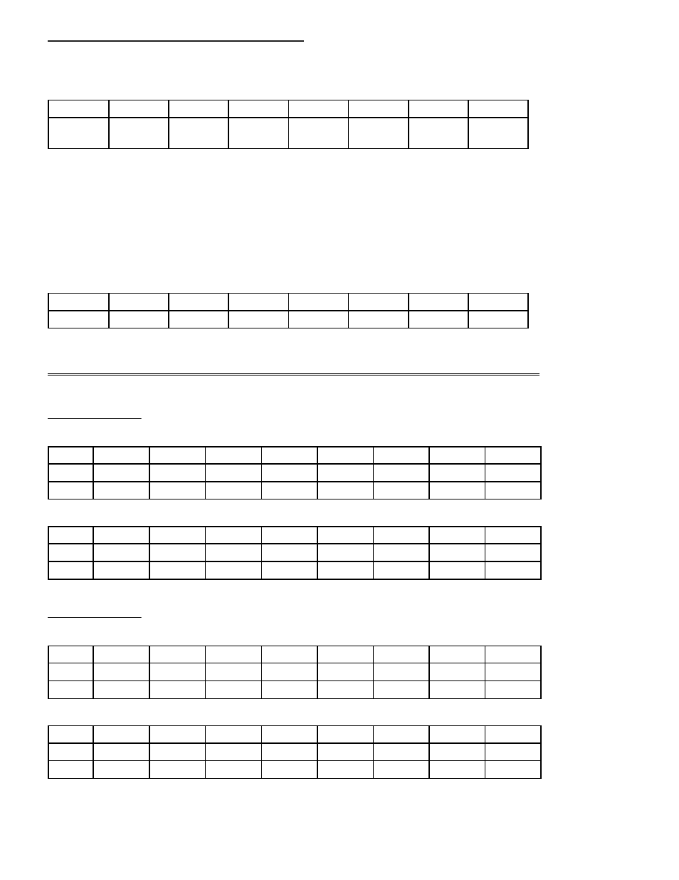
8-BIT DIGITAL I/O REGISTERS
BASE ADDRESS +3
Example, 303h, 771 Decimal
READ
DI0
XPACER
DI1
XTRIG
DI2
GATE0
DI3
DI4
DI5
DI6
DI7
0
1
3
2
4
5
6
7
The signals present at the 8 digital inputs are read as one byte. Three of the pins have special functions in addition to digital input.:
XPACER/DI0
External Pacer:
Starts an A/D Conversion on each active edge.
XTRIG/DI1
External Trigger:
Causes an entire acquisition to start or stop.
GATE0/DI2
Gate for CTR0
Used in Compatible mode only.
These special functions are optionally enabled in software, and are explained below. External Interrupt is enabled at BASE +9,
External Pacer and External Trigger are enabled at BASE +10. Please see those register descriptions for details.
WRITE
DO0
DO1
DO2
DO3
DO4
DO5
DO6
DO7
0
1
3
2
4
5
6
7
All of the eight bits are latched TTL outputs.
5.5
DIGITAL TO ANALOG CONVERTER (ANALOG OUT) REGISTERS
D/A 0 REGISTERS
BASE ADDRESS +4
Example, 304h, 772 Decimal
D/A0
D/A1
D/A2
D/A3
D/A4
D/A5
D/A6
D/A7
16-BIT
0
0
0
0
D/A0
D/A1
D/A2
D/A3
12-BIT
0
1
2
3
4
5
6
7
6402/
BASE ADDRESS +5
Example, 305h, 773 Decimal
D/A8
D/A9
D/A10
D/A11
D/A12
D/A13
D/A14
D/A15
16-BIT
D/A4
D/A5
D/A6
D/A7
D/A8
D/A9
D/A10
D/A11
12-BIT
0
1
2
3
4
5
6
7
6402/
D/A 1 REGISTERS
BASE ADDRESS +6
Example, 306h, 774 Decimal
D/A0
D/A1
D/A2
D/A3
D/A4
D/A5
D/A6
D/A7
16-BIT
0
0
0
0
D/A0
D/A1
D/A2
D/A3
12-BIT
0
1
2
3
4
5
6
7
6402/
BASE ADDRESS +7
Example, 307h, 775 Decimal
D/A8
D/A9
D/A10
D/A11
D/A12
D/A13
D/A14
D/A15
16-BIT
D/A4
D/A5
D/A6
D/A7
D/A8
D/A9
D/A10
D/A11
12-BIT
0
1
2
3
4
5
6
7
6402/
WRITE ONLY
17