6 status register – Measurement Computing CIO-DAS6402/12 User Manual
Page 22
6402/12
Each 12 bit D/A output line has two 8-bit registers. The first contains the four least-significant bits of the data and four 'don't-care'
bits. The second register contains the eight most significant bits of the data.
Data can be written as two successive bytes or as one word. When two bytes are written, the lower address byte must be written
first, and then the higher byte, as the DAC output is updated when the higher byte is written.
When the data is written as a single word, the most significant bit of the DAC data is the most significant bit of the word. The
CPU will automatically write the data to the board as two successive bytes, writing the low and then the high byte.
6402/16
Each 16-bit D/A output line has two 8-bit registers. The first contains the eight least significant bits of the data and the second
register contains the eight most significant bits of the data. The data is written as two successive bytes - the lower first (or LSB's)
followed by the higher byte (or MSB's).
The 6402/16 also has a jumper (HD1) to select either individual update (UPDATE) or simultaneous updating (XFER) of both
DAC's. In UPDATE mode, when the higher address is written, that DAC is updated. In XFER mode, after both DAC's are loaded,
a Read cycle to any of the DAC registers with update both DAC's simultaneously.
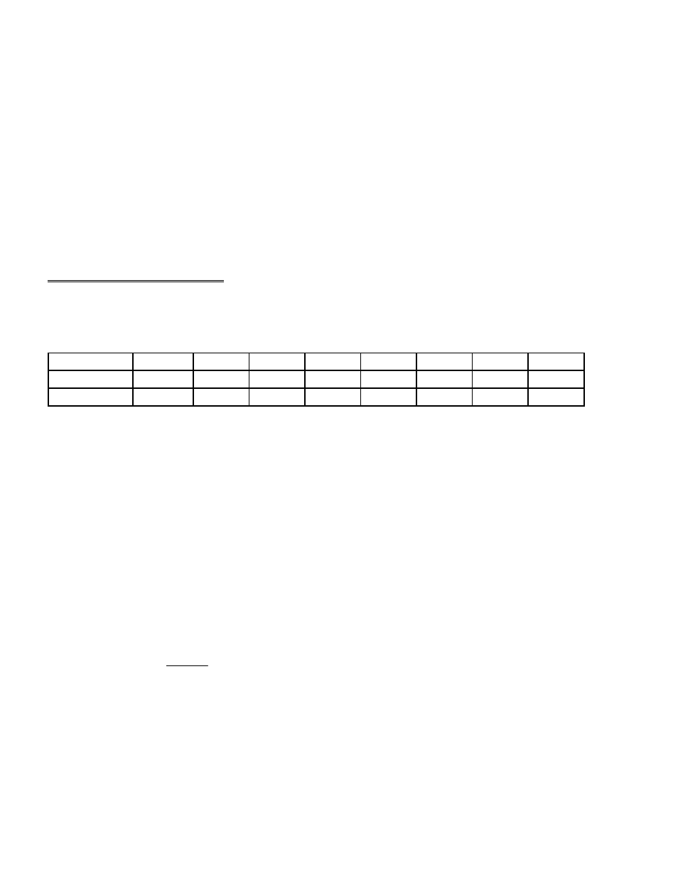
5.6
STATUS REGISTER
BASE ADDRESS + 8
Example, 308h, 776 Decimal
READ
MA0
MA1
MA2
MA3
INT
SEDIFF
UNIBIP
EOC
COMPATIBLE
FFNE
FHALF
FFULL
XINT
INT
XTRIG
INDGT
1/10MHz
ENHANCED
0
1
2
3
4
5
6
7
Mode
Description of Status Register read bits:
ENHANCED MODE:
1/10MHz - Internal Pacer clock source. = 1, Pacer clock is 10MHz, = 0, Pacer clock is 1MHz.
INDGT - Index Gate. Signals when the index counter has been shut off due to FIFO going Half Full. When = 0, index counter
active or flip-flop has been reset (by CLRXTR). When = 1, index counter has been shut off.
XTRIG - State of external trigger flop, used when edge-triggering. When =1, the trigger has been activated. When = 0 idle or not
active. Cleared by CLRXTR.
INT - State of interrupt flop, from 1 of 4 sources on the board. When = 1, the flip-flop indicates an interrupt condition. When = 0
no interrupt. Cleared by CLRINT. See BASE + 9 for interrupt enable and interrupt level and BASE + 11 for interrupt sources.
XINT - State of external interrupt flop, acts independently of on-board interrupt sources. When = 1, external interrupt occurred,
When = 0 no external interrupt. Cleared by CLRXIN.
FFULL - latched status of FIFO Full condition.
When = 1, FIFO exceeded full state, data may have been lost. When = 0, FIFO has not exceeded full state.
FHALF - indicates if FIFO is above or below half-full. Can be used as an interrupt source for REP INSW ADC.
When = 1, FIFO is above half-full. When = 0, FIFO is at or below half-full. (not latched)
FFNE - Not empty state of FIFO. Can be used as interrupt for single conversion ADC mode.
When = 1, FIFO is not empty (contains ADC data). When = 0, FIFO is empty (has no ADC data).
COMPATIBLE MODE:
EOC - End-of-conversion, When 1 = busy. When = 0, conversion complete.
UNIBIP - Analog input Unipolar/Bipolar status, When 1 = unipolar. When 0, = bipolar.
18