Measurement Computing CIO-DAS6402/12 User Manual
Page 27
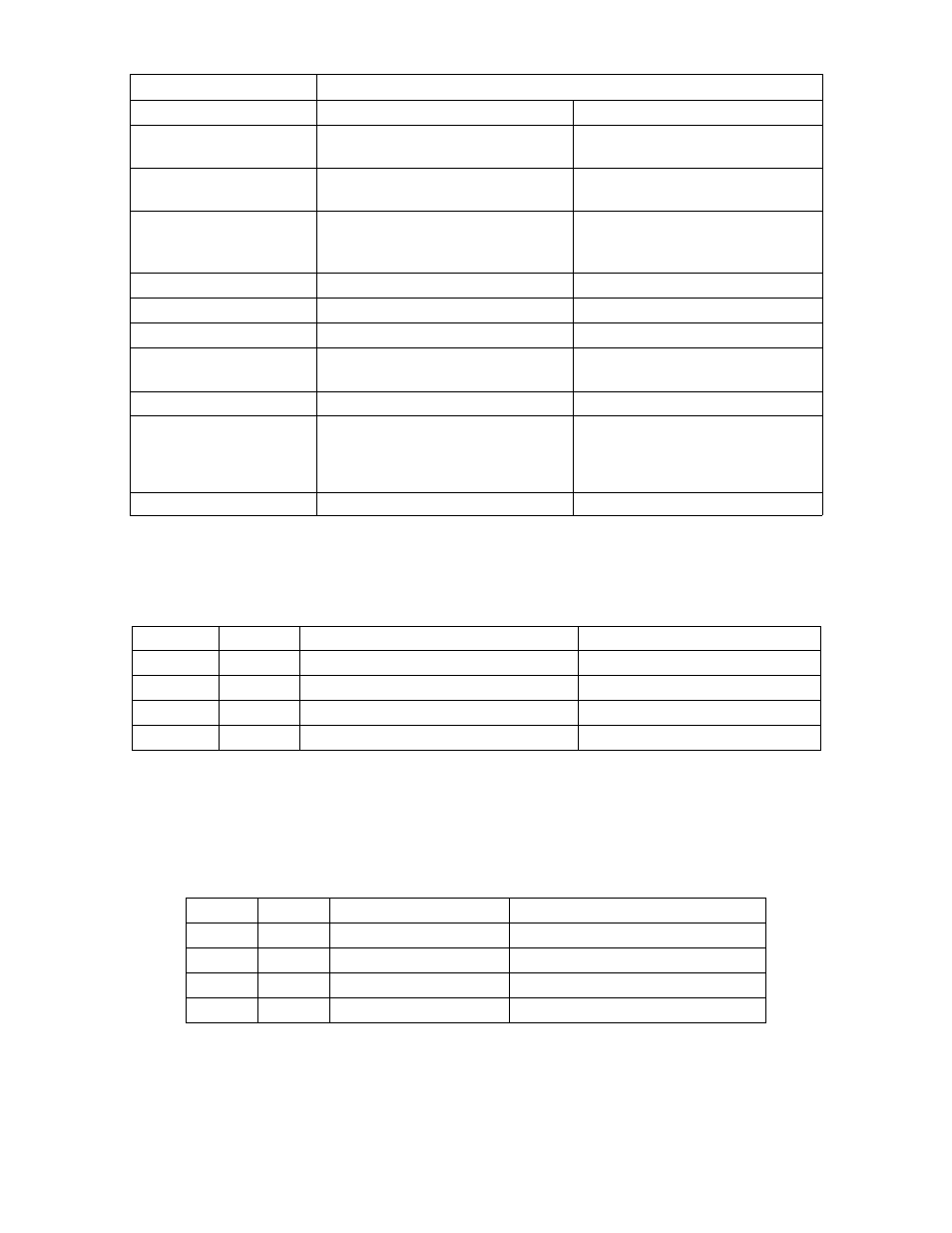
Table 5-7. Comparison of Features: Compatible vs. Enhanced Mode
Yes
No
Pre-trigger
Single ADC
REP INSW
End of Burst
External
Single ADC
DMA
Interrupts
Yes
Yes
Burst Mode
no, CTR0 used for pre-triggering
yes, CTR0
Independent Counter at user
connector
yes
no
REP INSW
no
yes
DMA
Separate from Trigger, uses DIN0
Combined w/ Trigger on DIN1
External Pacing
Separate from Pacing, uses DIN1.
Can be gate (level) or trigger
(edge)
Combined w/ Pacing on DIN1, gate
only
External Triggering
8 in
8 out
4 in
4 out
# Digital I/O
64 S-E
32 Diff
16 S-E
8 Diff
# Analog Input Channels
Enhanced
Compatible
MODE
Feature
In Enhanced mode, HC_AI1, HC_AI0 select the interrupt source, which also will determine the acquisition mode the board is to
be operated under. These bits are 0 in Compatible mode. Refer to Table 6-8.
Table 5-8. Interrupt Source Coding - Enhanced Mode
End of Burst
Burst REP INSW ( 2-64 samples)
1
1
FIFO ½ Full
Fifo REP INSW (512 samples)
0
1
FIFO Not Empty
Single ADC interrupt
1
0
none
Single ADC polled
0
0
Interrupt Source
ADC Acquisition Mode
HC_AI0
HC_AI1
If pre-trigger is enabled, (allowed during a REP INSW mode, HC_AI1=1) then an End-of-Acquisition interrupt will be enabled.
This interrupt occurs a pre-determined number of conversions after the trigger. Counter 0 is programmed to count conversions after
the trigger and will cause the interrupt when it counts down and reaches Terminal Count.
GAIN1, GAIN0 select the front end gain (Table 5-9). They are valid for Enhanced or Compatible Mode.
Table 5-9. Front-End Gain Coding
0 to 1.25V or ±1.25V
8
1
1
0 to 2.5V or ±2.5V
4
0
1
0 to 5V or ±5V
2
1
0
0 to 10V or ±10V
1
0
0
Analog Input Voltage Range
Analog Input Gain
GAIN0
GAIN1
23