Analog output, Digital i/o – Measurement Computing USB-1208FS User Manual
Page 22
USB-1208FS User's Guide
Specifications
22
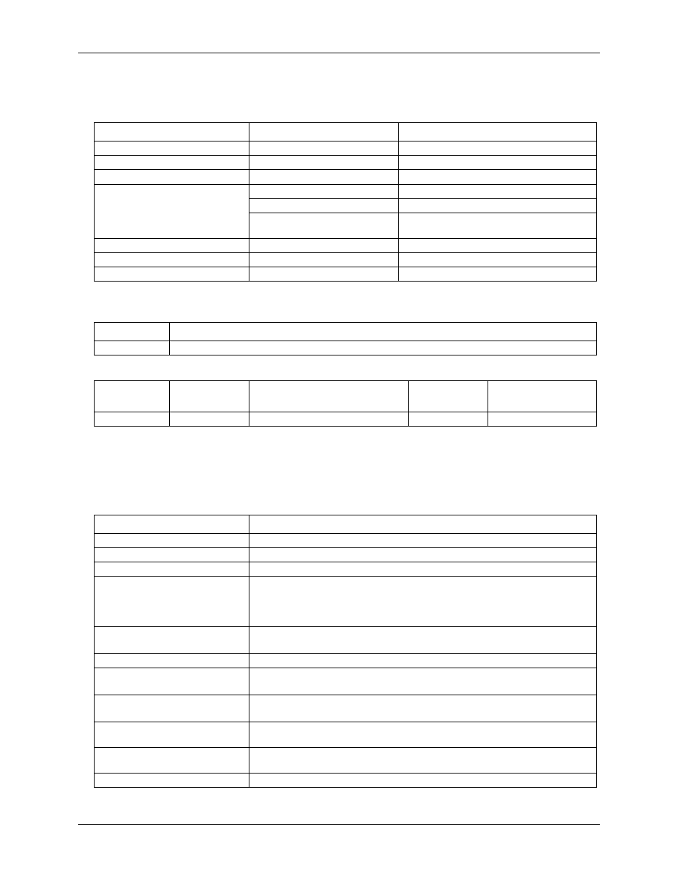
Analog output
Table 8. Analog output specifications
Parameter
Conditions
Specification
Resolution
12-bits, 1 in 4096
Output range
0 V to 4.096 V, 1 mV per LSB
Number of channels
2
Throughput (Note 4)
Software paced
250 S/s single channel typical, PC dependent
Single channel, continuous scan
10 kS/s
Dual channel, continuous scan,
simultaneous update
5 kS/s
Power on and reset voltage
Initializes to 000h code
Output drive
Each D/A OUT
15 mA
Slew rate
0.8V/microsecond (µs) typ
Note 4:
Maximum throughput scanning to PC memory is machine dependent.
Table 9. Analog output accuracy, all values are (±)
Range
Accuracy (LSB)
0 V to 4.096 V
4.0 typ, 45.0 max
Table 10. Analog output accuracy components, all values are (±)
Range
% of FSR
Gain Error at FS (mV)
Offset (mV)
(Note 5)
Accuracy at FS
(mV)
0 V to 4.096 V
0.1 typ, 0.9 max
4.0 typ, 36.0 max
1.0 typ, 9.0 max
4.0 typ, 45.0 max
Note 5:
Negative offsets will result in a fixed zero-scale error or "dead band." At the maximum offset of
–9 mV, any input code of less than 0x009 will not produce a response in the output.
Digital I/O
Table 11. Digital I/O specifications
Parameter
Specification
Digital type
CMOS
Number of I/O
16 (Port A0 through A7, Port B0 through B7)
Configuration
2 banks of 8
Pull up/pull-down configuration
All pins pulled up to 5V via 47 k
Ω resistors (default).
Hardware revisions D and later may be changed to pull-down using an internal
user-configurable jumper.
Previous revisions can be configured at the factory for pull-down.
Input high voltage threshold
2.0 V min
Input high voltage limit
5.5 V absolute max
Input low voltage threshold
0.8 V max
Input low voltage limit
–0.5 V absolute min
0 V recommended min
Output high voltage
(IOH = –6.0 mA)
3.84 V min
Output low voltage
(IOL = 6.0 mA)
0.33 V max
Power on and reset state
Input