Pin auxiliary connector (j9) – Measurement Computing USB-2020 User Manual
Page 13
USB-2020 User's Guide
Functional Details
40-pin auxiliary connector (J9)
The 40-pin auxiliary connector provides the following connections for all I/O signals except for analog input
and clock I/O:
Eight digital I/O (
DIO0
to
DIO7
)
Digital trigger input (
TRIG
IN
)
12 ground connections (
GND
)
Two +5V power outputs (
+VO
)
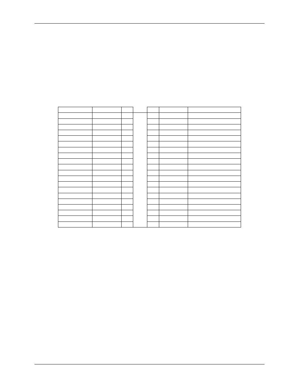
The signals that are available on the 40-pin IDC connector are listed below. Connect signals on the 40-pin IDC
connector using a C40FF-x cable or C40-37F-x cable.
40-pin IDC connector pin out
Pin Description
Signal Name
Pin
Pin
Signal Name
Pin Description
Ground
GND
1
•
•
2
+VO
Power output
Ground
GND
3
•
•
4
N/C
Do not connect
Digital I/O bit 7
DIO7
5
•
•
6
N/C
Do not connect
Digital I/O bit 6
DIO6
7
•
•
8
N/C
Do not connect
Digital I/O bit 5
DIO5
9
•
•
10
TRIG IN
External digital trigger input
Digital I/O bit 4
DIO4
11
•
•
12
GND
Ground
Digital I/O bit 3
DIO3
13
•
•
14
GND
Ground
Digital I/O bit 2
DIO2
15
•
•
16
GND
Ground
Digital I/O bit 1
DIO1
17
•
•
18
GND
Ground
Digital I/O bit 0
DIO0
19
•
•
20
GND
Ground
Ground
GND
21
•
•
22
N/C
Do not connect
Do not connect
N/C
23
•
•
24
N/C
Do not connect
Ground
GND
25
•
•
26
N/C
Do not connect
Do not connect
N/C
27
•
•
28
N/C
Do not connect
Ground
GND
29
•
•
30
N/C
Do not connect
Do not connect
N/C
31
•
•
32
N/C
Do not connect
Ground
GND
33
•
•
34
N/C
Do not connect
Power output
+VO
35
•
•
36
N/C
Do not connect
Ground
GND
37
•
•
38
N/C
Do not connect
Do not connect
N/C
39
•
•
40
N/C
Do not connect
13