Trigger input – Measurement Computing USB-2020 User Manual
Page 16
USB-2020 User's Guide
Functional Details
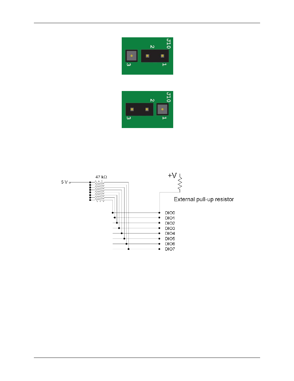
Pull-up default configuration (factory default)
Pull-down configuration
Figure 6. Pull-up and pull-down jumper configurations (J10)
An external pull-up resistor can be used to pull the DIO bit up to a voltage that exceeds the internal 5 V pull-up
voltage (15 V maximum). Be aware that this would place the 47k internal pull up resistor in a parallel
resistance configuration that could offset the logic high voltage level.
Figure 7. Digital I/O external resistor configuration
Trigger input
Both the
TRIG IN
BNC connector and the
TRIG IN
IDC pin are external digital trigger/gate inputs that you can
configure through software.
An analog scan can have a trigger or a gate, but not both. For example, you cannot use an analog trigger and use
the
TRIG IN
BNC connector to gate at the same time.
A trigger or gate can be digital or analog.
Digital triggers can be configured for rising or falling edge, or for high or low level.
Analog triggers can be configured for software-selectable high or low level, or for rising or falling edge
with software-selectable hysteresis.
Digital gates can be configured for high or low level.
Analog gates can be configured for software-selectable high or low level, or for in or out of software-
selectable window.
16