Caution – Measurement Computing ZonicBook 618E rev.3.4 User Manual
Page 115
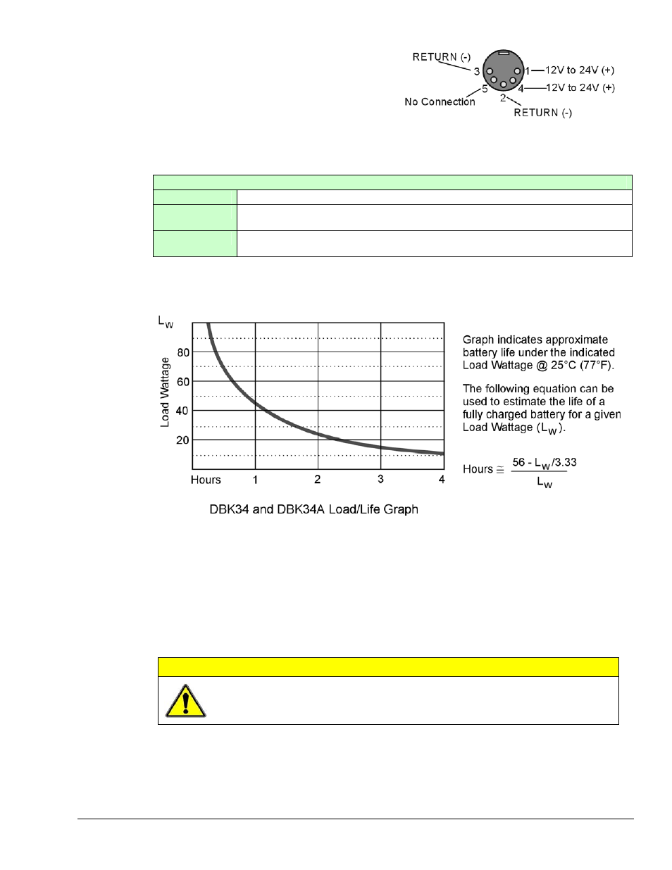
Power Out. The pinout at the right applies to the
two POWER OUT DIN5 connectors. The DBK34A
package includes a short connecting cable to
connect to the powered device. This cable connects
the POWER OUT connector on the DBK34A and
to the POWER IN connector on the acquisition
device; e.g., ZonicBook/618E, WaveBook,
LogBook, DaqBook, or WBK/DBK module.
DIN5 Power Output Connector
(2 per DBK34A)
Indicators. Three front-panel LED indicators provide power and charging status information.
LED Indicators & Descriptions
MAIN POWER
Lights when the DBK34A power input is connected to a source of at least 12.25 VDC
CHARGING
Lights when the internal batteries are being fast-charged at a rate of 0.1 amp/cell or
greater.
DISCHARGING
Lights when internal batteries (or auxiliary batteries) are discharging at a rate of 0.25A
or greater.
Runtime. Approximate runtime under various loads can be computed from the storage capacity
(5 A-hr in 12 V mode; 2.5 A-hr in 24 V mode) and the load (main unit and other DBKs).
The following Load Wattage vs. Hours graph is for a typical new battery that is fully charged.
Charging: In general, lead-acid batteries [and related Gel-Packs] require charging at 120% of drain energy
(e.g., the 5 A-hr DBK34A requires a charge equal to or greater than 6 A-hr). Charging times vary; but 4 to
5 hours at 14 V is typical for a completely discharged battery; after which, charging may continue
indefinitely.
Note that 16 to 18 VDC at the power input is required for optimal charging.
CAUTION
Voltage applied to a DBK34A must not exceed 30 VDC.
Appendix C
977995
Power Options C-7