The daisy-chain concept, How channel numbers are determined – Measurement Computing WaveBook rev.5.3 User Manual
Page 46
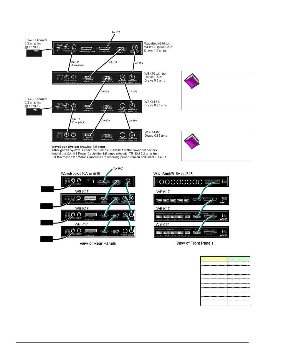
The Daisy-Chain Concept
Reference Note:
For information regarding
calculating system power
requirements, refer to the
upcoming section entitled,
Connecting the System to
Power.
Reference Note:
Refer to Chapter 3 for
additional system
examples.
Example of a WaveBook Daisy-Chain with three WBK17 Modules
Unit*
Channel #
WaveBook
0 (dig I/O)
WaveBook 1-8
1
st
WBK
9-16
2
nd
WBK
17-24
3
rd
WBK
25-32
4
th
WBK
33-40
5
th
WBK
41-48
6
th
WBK
49-56
7
th
WBK
57-64
8
th
WBK
65-72
How Channel Numbers are Determined
The analog input channel numbers are determined by the order of connection among the
WaveBook and attached WBK modules.
•
Channel 0 is the WaveBook’s 8-bit digital I/O port.
•
Channels 1 through 8 are the WaveBook’s main channels.
•
Channels 9 through 16 are located on the first expansion unit connected directly
to the WaveBook.
•
Additional channel numbers are added consecutively (in groups of 8)
with each added WBK module (see table at right).
* WBK in the “Unit” column refers to a module such as a WBK10A, WBK14, WBK15, WBK16, WBK17, WBK18.
Note that as this document goes to print the channel numbering method has not been determined for the WBK40 and
WBK41 modules.
WaveBook/512A, WaveBook/512A,
CA-150
CA-217
CA-129
2-26 System Setup and Power Options
979194
WaveBook User’s Manual