Appendix d -9513, Appendix d daq9513… commands d – Measurement Computing Data Acquisition Systems rev.10.4 User Manual
Page 341
Appendix D daq9513… Commands
D
API Programming Model for 9513 Counter-Timer Chip Devices
…… D-1
daq9513GetHold
…… D-3
daq9513MultCtrl
…… D-4
daq9513SetAlarm
…… D-6
daq9513SetCtrMode
…… D-7
daq9513SetHold
…… D-12
daq9513SetLoad
…… D-13
daq9513SetMasterMode
…… D-14
This appendix only applies to product versions that make use of a 9513 counter-timer chip.
The 9513 counter-timer chip devices include the following:
•
DaqBook/100 Series
•
DaqBook/200 Series
•
DaqBoard/100 Series
•
DaqBoard/200 Series
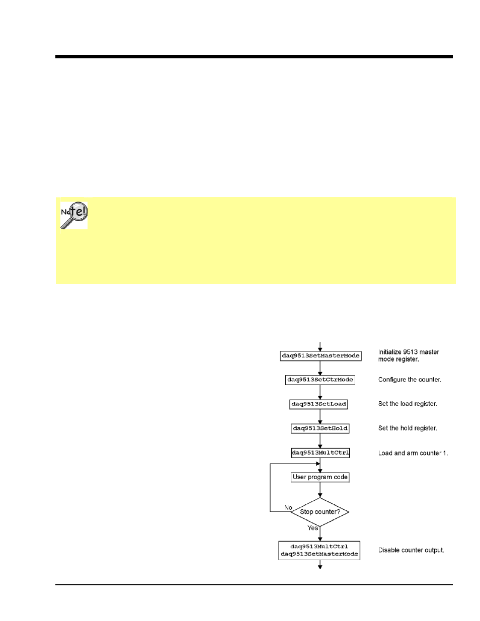
API Programming Model for 9513 Counter-Timer Chip Devices
Variable Rate, Variable Duty-Cycle Square-Wave Output
This section demonstrates the use of the counter/timer
section of a DaqBook/100/200 or of a
DaqBoard/100A/200A with the P3 port. After
configuring the counter and setting the load and hold
registers, the counter is armed. At this point, program
execution continues while the counter outputs the signal.
This example generates a variable rate, variable duty-
cycle square wave. Functions used include:
•
Vbdaq9513SetMasterMode&(handle&,deviceType&
,whichDevice&,foutDiv&, cntSource&, comp1&,
comp2&, tod&)
•
Vbdaq9513SetCtrMode&(handle&,deviceType&,wh
ichDevice&, ctrNum&,gayeCtrl&, cntEdge&,
cntSource&, specGate&, reload&, cntRepeat&,
cntType&, cntDir&, outputCtl&)
•
Vbdaq9513SetHold&(handle&,
deviceType&,whichDevice&, ctrNum&, ctrVal%)
•
Vbdaq9513SetLoad&(handle&,deviceType&,which
Device&, ctrNum&, ctrVal%)
•
Vbdaq9513MultCtrl&(handle&,deviceType&,whic
hDevice&, ctrCmd&, ctr1&, ctr2&, ctr3&,
ctr4&, ctr5&)
Programmer’s Manual
938295
9513 Counter-Timer Commands D-1