Installation and setup – Metro 4 Series Insulation Armour Plus Hot food Holding Cabinets User Manual
Page 4
4
INSTALLATION AND SETUP
1. Check the packaging and cabinet for shipping damage after unloading the unit, and after removing all the
packaging.
2. The receiver of this product is responsible for filing freight damage claims. This equipment must be opened
immediately for inspection. All visible damage must be reported to the freight company within 48 hours and must be
noted on freight bill at the time of delivery.
3. Concealed damage is your responsibility — you must advise the carrier of any loss or damage within 15 days after
receipt of the cabinet. If there is damage, retain the original packaging for inspectors.
4. Any protective covers (plastic or paper sheet) on the sheet metal, if applicable, must also be removed before turning
the cabinet on.
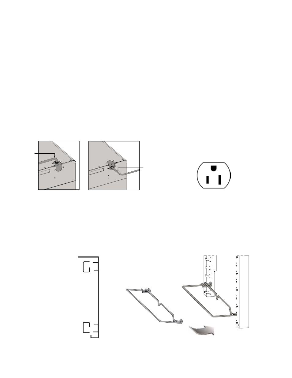
5. To change the position of the power cord, first make sure the cabinet power switch is off and the power cord is
unplugged from any electrical outlet. Remove the screws holding the cabinet top in place. Remove the screws on
the rear of the cabinet that hold the cord bracket in place. Rotate the power cord bracket 90° to the desired position
and reattach it with the screws to the back of the cabinet. Make sure the green ground wire connection and the
wire nuts on the black and white wires have not loosened. Do not alter the wiring of the power cord to the cabinet.
Replace the cabinet top and the screws holding it in place.
6. Refer to the data plate located near the power cord for the electrical specifications of the cabinet as shown on Page 2.
◦◦ With◦the◦POWER◦switch◦OFF,◦plug◦the◦cord◦into◦the◦appropriate◦rated,◦grounded◦receptacle.
◦◦ Cabinets◦rated◦at◦120V◦1400W◦must◦be◦plugged◦into◦15◦amp◦125◦VAC◦receptacle.
WARNING: Do not allow combustible materials to be stored or accumulate on, under or next to the cabinet. Do not
block any ventilation louvers or slots.
CAUTION: Allow 18" (46cm) between the Armour panels and any cooking equipment. Do not allow hot kitchen
equipment whose surfaces exceed 200°F (90°C) to touch the panels.
SLIDE INSTALLATION
FIGURE 1:
POWER CORD LOCATION ON CABINET
FIGURE 2:
WALL RECEPTACLES
The universal rack
uprights or lip load
slides have been
installed at the factory.
If removed for cleaning,
reinstall by hanging
them on the rack
hangers on the side
walls of the cabinet.
Cord Out
of the Top
Cord Out
of the Back