Wiring the fault alarm contact, Led indicators – Microsens MS655200 User Manual
Page 10
7
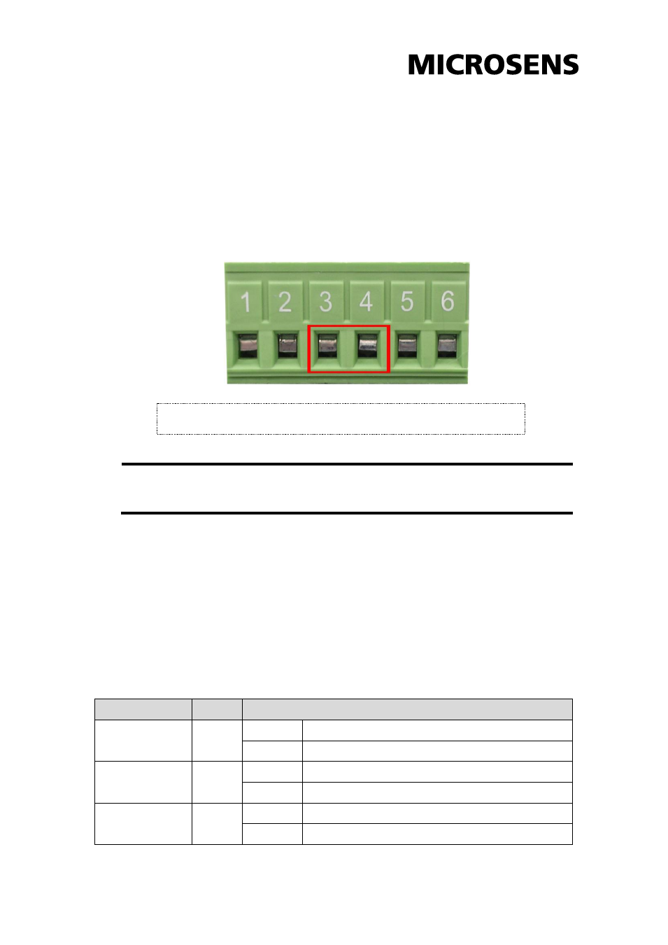
Wiring the Fault Alarm Contact
The fault alarm contact is in the middle of terminal block connector as the
picture shows below. Inserting the wires, it will detect the fault status
which the power is failure or port link failure (for managed model) and form
an open circuit.
Note
The wire gauge for the terminal block should be in the range
between 12~ 24 AWG.
LED Indicators
There are few LEDs display the power status and network status
located on the front panel of the Industrial switch, each of them has its
own specific meaning as below table.
LED
Color
Description
P1
Green
On
Power input 1 is active
Off
Power input 1 is inactive
P2
Green
On
Power input 2 is active
Off
Power input 2 is inactive
Fault
Red
On
Power input 1 or 2 is inactive
Off
Power input 1 and 2 are both functional, or no power
Insert the wires into the fault alarm contact (No. 3 & 4)