Microsonic sks-15/CI User Manual
Microsonic Sensors
Sensor adjustment with Teach-in procedure
Set window margins
Place object at position
➀
Press push-button for about 3 s until LEDs
flash
simultaneously
both LEDs:
Place object at position
➁
Set rising/falling output
characteristic curve
Press button for about 13 s until LEDs
flash
mutually
flash
mutually
green LED:
yellow LED:
flashes
on: rising
off: falling
characteristic curve
Enable/disable Teach-in push-
button
Switch off power supply
Reset to factory setting
Switch off power supply
While pressing the push-button
switch on power supply
Keep push-button pressed for
about 3 s until both LEDs flash
simultaneously
green LED:
yellow LED:
flashes
on: push-button
enabled
off: push-button
disabled
While pressing the push-button
switch on power supply
Keep push-button pressed for
about 13 s until both LEDs stop
flashing
Press push-button for
about 1 s
Normal operating mode
To change output characteristic press
push-button for about 1 s
Wait for 10 s
To enable/disable Teach-in press
push-button
for about 1 s
Wait for 10 s
Normal operating mode
Operating Instructions
sks-15/CI
sks-15/CU
Ultrasonic proximity switch with
one analogue output
Ultrasonic Sensors
Product Description
The sks sensor offers a non-contact
measurement of the distance to an
object which must be positioned
within the sensor’s detection zone.
Depending on the set window limits,
a distance-proportional analogue sig-
nal is output.
Via the push-button, the detect dis-
tance and operating mode can be
adjusted (teach-in). Two LEDs indi-
cate operation and the state of the
output.
Safety Notes
■
Read the operating instructions
prior to start-up.
■
Connection, installation and
adjustment works may only be
carried out by expert personnel.
■
No safety component in
accordance with the EU Machine
Directive.
Proper Use
sks ultrasonic sensors are used for
non-contact detection of objects.
Installation
■
Mount the sensor at the installa-
tion site.
Maximum torque of screws:
0,5 Nm
■
Connect a connection cable to the
M8 device plug.
Fig. 1: Pin assignment with view onto sensor
plug and colour coding of the
microsonic connection cable
Start-Up
■
Connect the power supply.
■
Carry out the adjustment in
accordance with the diagram.
Factory Setting
■
Rising analogue characteristic
curve between the blind zone and
the operating range.
1
3
colour
+U
B
-U
B
brown
blue
4
2
D
Com
black
white
1
4
3
2
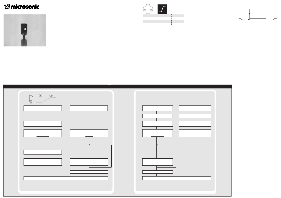
Synchronization
If several sensors are mounted close
to another, they should be synchroni-
zed with each other. This is done by
an externally provided synchronisati-
on signal.
■
Apply a square-wave signal to the
sync-input with pulse width t
i
and
repetition rate t
p
(Fig. 3 and
technical data).
Any amount of sensors may be syn-
chronized with this external synchro-
nisation signal.
A high level on the sync-input will
deactivate the sensor.
Fig. 3: External synchronization signal
Maintenance
microsonic sensors are maintenance-
free. In case of excess caked-on dirt
we recommend cleaning the white
sensor surface.
Notes
■
The sks sensor uses an internal
temperature sensing element to
compensate the temperature de-
pending speed of sound. In the
first 45 seconds after power on
every time the sks tests this tem-
perature compensation and after-
wards sets the analogue output
according to the compensated dis-
tance value.
■
The temperature compensation
automaticly adjusts to the actual
mounting conditions if the sensor
outputs current of 11 to 13 mA or
voltage of 4.4 to 5.6 V for at least
30 minutes after switching on
power supply.
■
The sks sensor has a blind zone,
within which distance measure-
ments are not possible.
■
In the normal operating mode, an il-
luminated yellow LED signals that the
object is within the adjusted win-
dow limits.
■
If the push-button is not pressed
for 30 seconds during the teach-in
setting, the settings made hitherto
are deleted.
■
The sensor can be reset to its fac-
tory setting (s. »Further settings«).
Sensor disabled
Sensor disabled
Start
+U
B
-U
B
t
i
t
p
Set analogue output
Further settings