3 front panel, Status monitoring – Nevion WOS-2 User Manual
Page 11
WOS-2
Rev. H
nevion.com | 11
Max output current: 100mA
Max output voltage: 30V
WOS-2x1/WOS-2x2 GPI pinning:
Signal
Name
Pin #
Input/Output
Mode
Status
General error status for the module
Pin 1
Output
Open Collector
Standby Alarm when switch in standby mode
Pin 2
Output
Open Collector
Switch to standby mode
Pin 5
Input
0V= standby
5V= main
Reset switch to main position
Pin 6
Input
Reset switch to main position
Pin 7
Input
Ground
0 volt pin
Pin 8
0V
The switch is set in standby mode by sinking pin5 to ground. Pin6 and pin7 are hardwired as
logical OR and when either is sunk to ground, they will reset the latching switch to main
position. Resetting can also be done with GYDA system controller
Figure 10: GPI Outlet
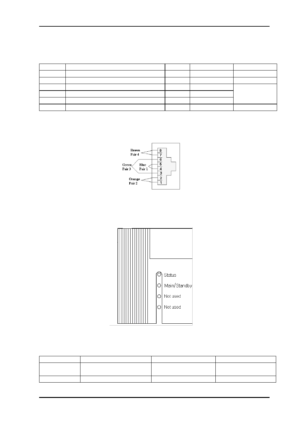
5.1.3 Front Panel
– Status Monitoring
The status of the module can be easily monitored visually by the LEDs at the front of the
module. The LEDs are visible through the front panel as shown in Figure 9
Figure 11: Diode overview of WOS-2x1(L)/WOS-2x2(L)
Both WOS-2x1(L) and WOS-2x2(L) have 2 LEDs each showing a status corresponding to
the GPI outputs.
Diode \ state
Red LED
Green LED
No light
Status
Module is faulty
Module is OK
Module power is OK
Module has no power
Main/standby
Switch in standby position
Switch in main position